Product Overview#
SPI Rack#
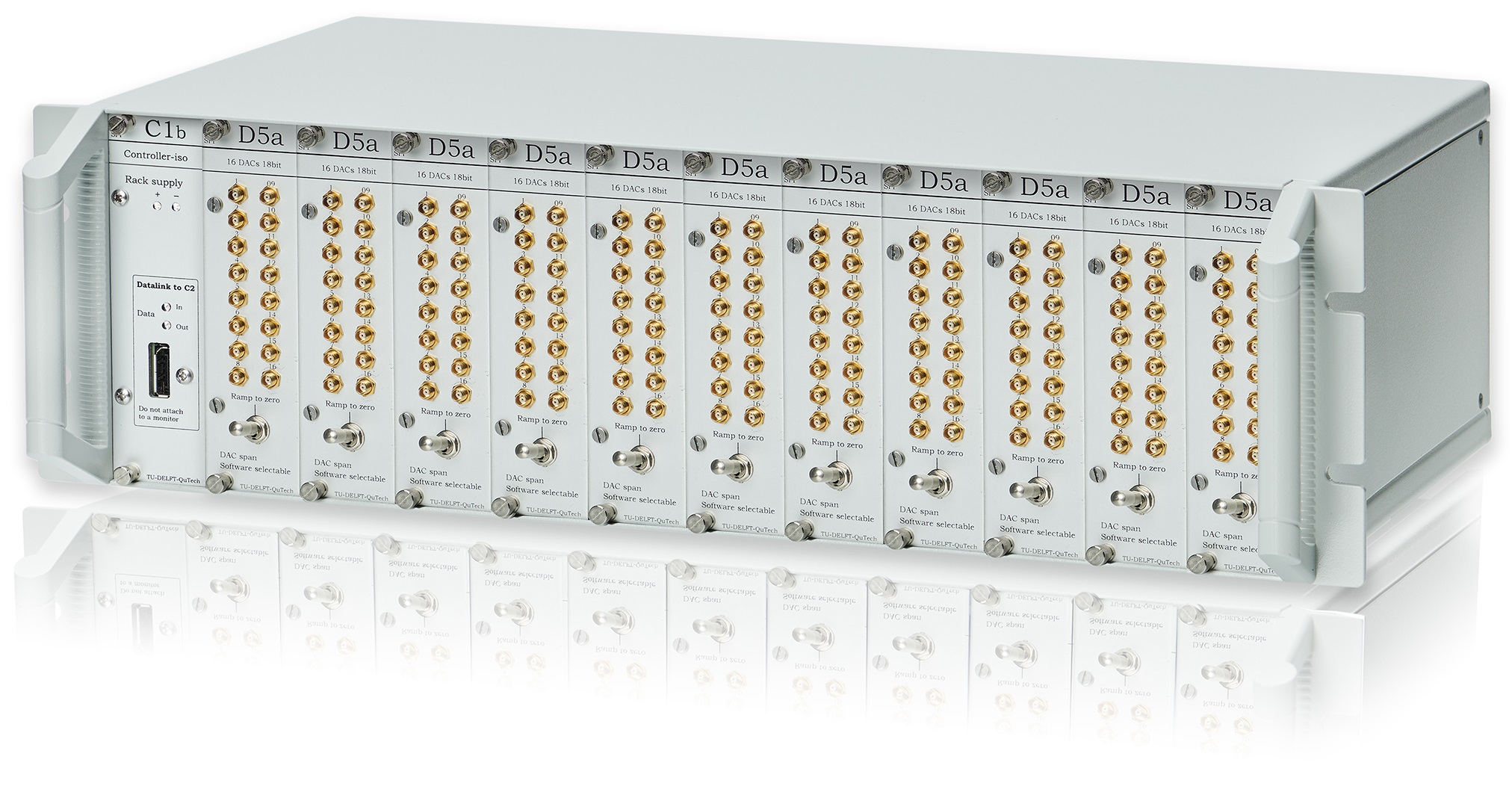
The SPI Rack is an ultra stable and extremely low noise modular system for DC current and DC voltage source modules. Modules are designed to maximize output stability. Together with the galvanically isolated control interface and isolated power supply, ground loops are avoided and interference (like 50 Hz) is minimized.

Along with the SPI rack, the full SPI setup makes up of the following components listed below:
SPI rack chassis
External Power Supply
Gyrator
Ferrite core
Battery unit
Display port cable
USB cable
To setup each component in the SPI properly to complete the setup, please go to SPI setup.
The SPI rack houses the following modules:
C1b: Isolated controller which consists of two parts;
C1b which is the controller module and is inserted in the left most slot inside the SPI rack.
C2 which is an isolator box.
S4g: 4 channel DC current source and voltage monitor.
D5a: 16 channel DC voltage source.
For a description of each module of the SPI Rack setup, please go to SPI Rack.
SPI rack chassis#
The SPI rack may house up to 12 modules in a modular chassis which connects the housing modules via an integrated backplane. The integrated backplane provides digital communication and power to the modules. This communication is made through the C1b controller module which in turn establishes a connection between the SPI rack and the user PC. With the C1b controller necessary to establish such connection, there remains up to 11 D5a or S4g modules to be housed inside the SPI rack chassis. Note that the C1b controller module is always slotted in the leftmost slot inside the SPI rack chassis.
Further, the internal backplane has the following connections to the inserted modules in the chassis
SPI Bus - Handles the digital communication between all the modules.
Digital lines - Used to trigger multiple modules at the same time.
Power supply - Power to supply the modules.
The back of the SPI rack chassis hosts two sets of two power connections. The left hand side are the connections made from the SPI rack chassis to the batteries. The right hand side has two optional voltage connections with ±12 V and a user defined voltage. The boundaries of the user-defined voltage must be within the following boundaries: AC not over 24 V, DC not over ±24 V and the current should not exceed 1 A.
Note
Located in the middle of the back of the SPI rack chassis, are two copper grounding plates. These copper grounding plates must only be considered if the SPI rack is not able to be mounted anywhere else other than directly on a metal rack which is grounded. In this particular case, the copper grounding plates are utilized to create a low impedance path from the SPI rack to the fridge via a braided ground cable. Ground currents flowing via the signal cables from the modules, are now reduced as the connection between the grounding plates and the fridge offers an alternative current path.
Important
In the case of a single SPI rack chassis housing multiple S4g modules, there are currently setup differences to ensure the SPI setup is working and supplying the necessary amount to operate the S4gs at their maximum rating. Please see Setup with more than 5 S4gs for further details. Note that the SPI setup only supports up to 9 S4gs.
Power chain#
The power chain in the SPI setup consists of an external power supply unit (PSU), the gyrator and the battery unit. Together they are isolated from the SPI rack chassis which is ideal when conducting sensitive DC measurements.
External Power Supply unit#
The PSU is an external linear AC/DC power supply. The PSU provides the setup with a constant voltage and is avoiding ground loops and interference in combination with the gyrator. The table seen below are the required specifications of the PSU which is to be used as part of the SPI setup.
Important
The power supply has to be an AC/DC power supply with the characteristics in the table. Going beyond these specific requirements may result in insufficient supply of power and can also damage the connecting components within the setup.
External Power Supply Characteristics |
||
|---|---|---|
Input |
240 Vac |
|
Output |
2 outputs |
|
12 Vdc - 13.5Vdc / output |
||
2 A / output |
||
Type |
Linear Power Supply |
Switched-mode Power Supplies in general have too much noise on the output, and do not have ground-loop isolation, necessary for the application. |
Required standards |
Safety: IEC/EN 61010-1 |
|
EMC: IEC/EN 61326-1:
|
||
Gyrator#
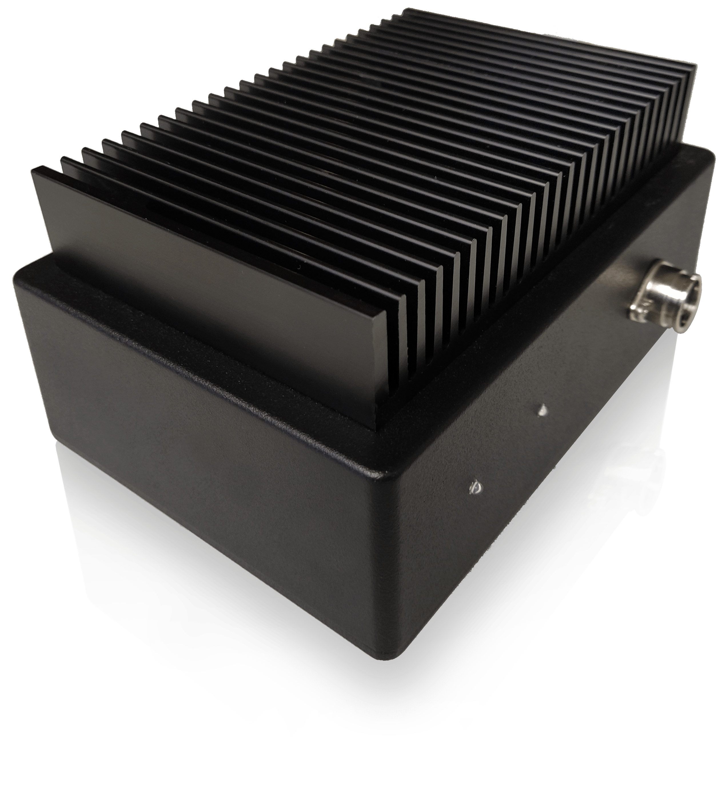
The gyrator is a box with a common mode choke and an active circuit which mimics a very large inductor of 40 H on every power lead. In the SPI rack setup, the gyrator is used to prevent interference signals of more than 50 Hz from getting to the SPI rack. The reason is that there are no physical connections between the mains ground and the SPI rack.

Battery unit#
The battery unit consists of two batteries each containing two 6 V lead acid batteries placed in a metal box with a capacity of 12 Ah. The fuses on the battery units prevent excessive currents above 6 A in the case of short circuit. The battery which is used in the enclosure can be seen here.
Displayport cable#
The displayport cable connects the C1b controller module to the C2 Isolator box and controls the communication between the modules inside the SPI rack to the C2 isolator box. Note the cable length of the displayport is vital to be kept as intended due to a circuit inside the C2 Isolator box tuned for the exact length of the displayport. For the required cable lengths used within the SPI setup, please go to Connecting the SPI components.
USB cable#
The USB connection is used to make the connection between the C2 Isolator box and the computer. This completes the connection between the SPI rack and your PC.