SPI setup#
This page, is dedicated to the installation steps for the various tools needed to operate on the SPI.
In addition, we will explain how to connect an SPI rack to your host PC. Before setting up the SPI rack, make sure that qblox_instruments Python driver is successfully installed,
which follows the same process as for the Qblox Cluster, seen on the page Setup.
Setting up the SPI Rack#
In this section we will go through the connections needed to establish the Qblox SPI Rack and how to connect it to the power chain and to your PC.
Connecting the SPI components#
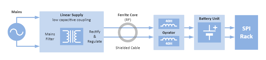
The components in the SPI setup are connected as seen in the schematic below.
Important
It is important that the components are connected in the order which the schematic illustrates.
The recommended way to connect the SPI Rack to power is by connecting it via a gyrator to mains in parallel to a battery. This will ensure the system remains powered and stable while the gyrator prevents interference signals such as 50 Hz from getting to the SPI Rack by mimicking a large (~40H) inductor.
Connecting to Power#
To connect the power to the SPI rack chassis, the power chain is connected to the back of the SPI rack chassis, specifically through the connectors on the left side on the SPI rack chassis.The left side of connectors on the back of the SPI rack chassis is the mandatory supply input. This implies that the connection is established from one of the connectors on the front of the battery pack, linking the SPI rack chassis to the power chain. Which of these two connectors does not matter as the two connectors are coupled internally.
Important
Make sure to always power ON the PSU first in the SPI setup, then turn the SPI rack switch ON. An indication of when to turn ON the SPI rack is to check that the two LEDs on the gyrator are green.
When turning off the SPI setup make sure to firstly switch the SPI rack OFF and then the PSU can be turned OFF. Otherwise the battery pack will supply power to the SPI rack instead which will slowly drain out the batteries, leaving the battery pack defected.
The battery is strongly advised to always be used in the SPI setup together with the PSU and the SPI rack. With the PSU being turned ON and the SPI rack switch turned ON in the advised order above, the batteries will be continuously charged in the SPI setup.
Important
When connecting each component in the SPI setup, each connection has a required cable type and length which can be seen in the following table.
Connection |
Cable type |
Cable length |
Comments |
|---|---|---|---|
PSU to Gyrator |
Shielded DC cable |
Less than 3m |
Special cable, sent with the product |
Gyrator to Battery |
Shielded DC cable |
Less than 3m |
Special cable, sent with the product |
Battery to Chassis |
Shielded DC cable |
Less than 3m |
Special cable, sent with the product |
C1b to C2 |
Displayport cable |
Less than 3m |
Normal displayport cable, specified less than 3m |
C2 to computer |
USB cable |
Less than 3m |
Normal USB cable, specified less than 3m |
Output cable |
Shielded MCX cable |
Less than 3m |
Specified less than 3m |
Note
The cable between the gyrator and the power supply also requires a minimum of 1 meter to effectively prevent interference signals from getting to the SPI Rack. Also, ensure that the SPI Rack is not mounted in the same 19-inch rack with line-powered equipment, this includes the gyrator power supply.
To complete the whole power chain setup to the SPI rack chassis, as shown in the schematic at Connecting the SPI components, make the following connections:
Connect the external PSU to one of the connectors of the gyrator using a shielded DC cable.
Connect the second connector of the gyrator to one of the front connectors on the battery pack. The battery has two connectors on the front of the battery pack.
Connect the second connector of the battery pack to the back of the SPI rack chassis.
The connection steps between the power chain and the SPI rack chassis are now completed.
Setup with more than 5 S4gs#
Important
When housing the SPI rack chassis with more than 5 S4gs with the current SPI setup, the setup must be extended by an additional PSU and a gyrator connected to one battery pack. In this case, the additional components will be provided by Qblox. The additional PSU and gyrator will now be able to support up to 9 S4gs, where each channel on the S4g is operating at the maximum rating i.e @ 40 mA at the given output voltage range of the PSU, see External Power Supply unit.
Connecting to PC#
To make a connection between the PC and the SPI rack, we utilize the C1b module to enable the connection that is the C1b controller module and the C2 isolator box.
Make sure the C1b controller module is fully inserted in the leftmost slot of the SPI Rack.
Then, connect the C1b to the C2 Isolator box via a displayport cable.
Now, connect the C2 SPI Isolator box via a USB cable to your PC.
Finally, make sure the power switch on the back of the SPI Rack chassis is in the ON position, and the power supply is switched ON as well. The power switch of the SPI is the left side switch above the left side connector output pair. The LED on the C1b module should now turn on.

On Windows systems, the SPI rack will now show up as a COM port in Windows Device Manager, while on OSX and Linux systems, it will show up in the /dev/ directory as /dev/ttyUSB#, /dev/ttyS# or /dev/cu# (where # is a number). Please note down the COM port or /dev address as we will use it later.
We can now connect to the SPI Rack via the QCoDeS driver provided through the qblox-instruments package (see section Installation).
Communicating with the SPI Rack#
Starting the communication with the SPI Rack is done by simply instantiating an instance of the driver:
from qblox_instruments import SpiRack
# Replace COM4 with the port that your SPI rack is connected to.
# On OSX and Linux systems, this will be of the form /dev/tty## or /dev/cu##
spi = SpiRack('SpiRack', 'COM4')
For each of the modules we intend to use, we should add to the driver. This is done simply by:
spi.add_spi_module(2, "S4g") # example for an S4g on address 2