Overview
In this section we will have a look at the Qblox instruments and their IO and shortly explain what they are for.
Pulsar
The Pulsar modules are compact qubit control and readout modules (QCM / QRM). They are conveniently controlled over Ethernet and are easily connected to your setup using SMA and SMP connectors. They are also easily combined with other Qblox instruments using Qblox’s SYNQ technology.
Front

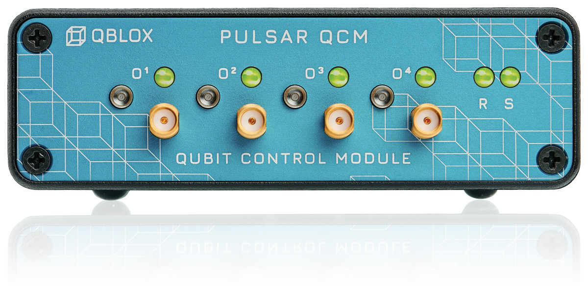
On the front of a Pulsar module you will find the following components:
4 x SMA male connectors: 4 output for a Pulsar QCM (O[1-4]: 5 Vpp @ 50 Ω) ; or 2 outputs and 2 input channels for a Pulsar QRM (O[1-2]: 1 Vpp @ 50 Ω, I[1-2]: 2 Vpp @ 50 Ω).
4 x SMP female connectors: Marker output channels (0-3.3 V TTL).
6 x status LEDs: See section Frontpanel LEDs.
Back

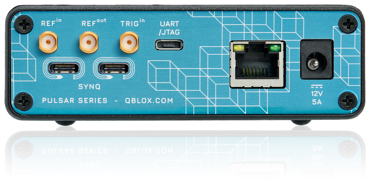
On the back of a Pulsar module you will find the following components:
Power: 12 V DC power supply input.
RJ45: Host PC connection.
3 x USB:
UART/JTAG: For debug purposes only.
2 x SYNQ: For synchronizing multiple Qblox instruments.
3 x SMA:
REFin: External 10MHz reference clock input (1 Vpp nominal @ 50 Ω).
REFout: 10MHz reference clock output (0-3.3 V @ 50 Ω).
TRIGin: External trigger input (0-3.3 V, high-Z).
SPI Rack
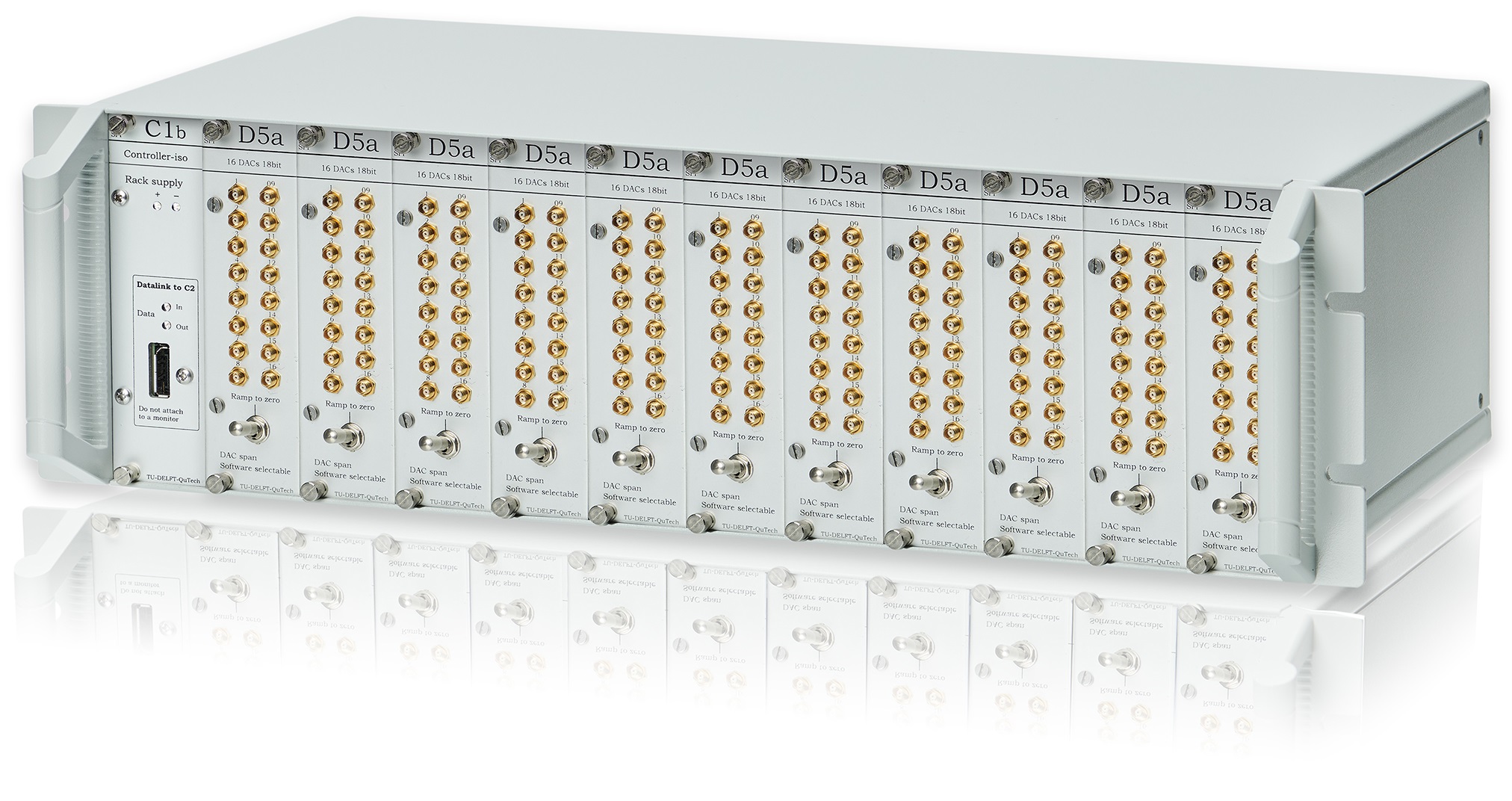
The SPI Rack is a modular system for DC current and DC voltage source modules. Modules are designed to maximize output stability. Together with our Galvanically isolated Control Interface and Isolated power supply ground loops are avoided and interference (like 50 Hz) is minimized.

S4g 4 channel current source

On the front of each S4g module you find:
4 x SMA: DC current source with software-selectable range: ±50 mA, ±25 mA, +50 mA, 18 bit resolution.
4 x MCX: Voltage monitor for each channel.
D5a 16 channel DAC

On the front of each D5a module you find:
16 x MCX: DC voltage source with software-selectable range (±4, ±2, +4 V), 18 bit resolution, 550 Ohm output impedance.
1 x switch: Switch to ramp all outputs down to zero volt.