See also
A Jupyter notebook version of this tutorial can be downloaded here.
NV Center Qubit#
Setup#
Imports#
[ ]:
from __future__ import annotations

from typing import TYPE_CHECKING, Callable

import matplotlib.pyplot as plt
import numpy as np
from qcodes.instrument.parameter import ManualParameter

if TYPE_CHECKING:
    from qblox_instruments.qcodes_drivers.module import Module

from qcodes.instrument import find_or_create_instrument

import quantify_core.visualization.pyqt_plotmon as pqm
from qblox_instruments import Cluster, ClusterType
from quantify_core.data import handling as dh
from quantify_core.measurement.control import MeasurementControl
from quantify_core.visualization.instrument_monitor import InstrumentMonitor
from quantify_scheduler import Schedule
from quantify_scheduler.backends import SerialCompiler
from quantify_scheduler.device_under_test.quantum_device import QuantumDevice
from quantify_scheduler.gettables import ScheduleGettable
from quantify_scheduler.instrument_coordinator import InstrumentCoordinator
from quantify_scheduler.instrument_coordinator.components.generic import (
    GenericInstrumentCoordinatorComponent,
)
from quantify_scheduler.instrument_coordinator.components.qblox import ClusterComponent
Scan For Clusters#
We scan for the available devices connected via ethernet using the Plug & Play functionality of the Qblox Instruments package (see Plug & Play for more info).
!qblox-pnp list
[ ]:
cluster_ip = None
cluster_name = "cluster0"
Connect to Cluster#
We now make a connection with the Cluster.
[ ]:
cluster = find_or_create_instrument(
    Cluster,
    recreate=True,
    name=cluster_name,
    identifier=cluster_ip,
    dummy_cfg=(
        {
            2: ClusterType.CLUSTER_QCM,
            4: ClusterType.CLUSTER_QRM,
            6: ClusterType.CLUSTER_QCM_RF,
            8: ClusterType.CLUSTER_QRM_RF,
        }
        if cluster_ip is None
        else None
    ),
)
Get connected modules#
[ ]:
def get_connected_modules(cluster: Cluster, filter_fn: Callable | None = None) -> dict[int, Module]:
    def checked_filter_fn(mod: ClusterType) -> bool:
        if filter_fn is not None:
            return filter_fn(mod)
        return True

    return {
        mod.slot_idx: mod for mod in cluster.modules if mod.present() and checked_filter_fn(mod)
    }
[ ]:
# QRM baseband modules
readout_modules = get_connected_modules(cluster, lambda mod: mod.is_qrm_type and not mod.is_rf_type)
readout_modules
[ ]:
readout_module = readout_modules[4]
[ ]:
# QCM baseband modules
control_modules = get_connected_modules(
    cluster, lambda mod: not mod.is_qrm_type and not mod.is_rf_type
)
control_modules
[ ]:
control_module = control_modules[2]
[ ]:
# QCM RF modules
rf_control_modules = get_connected_modules(
    cluster, lambda mod: not mod.is_qrm_type and mod.is_rf_type
)
rf_control_modules
[ ]:
rf_control_module = rf_control_modules[6]
[ ]:
from quantify_scheduler.helpers.mock_instruments import MockLocalOscillator

lo_readout_laser = find_or_create_instrument(
    MockLocalOscillator, recreate=True, name="lo_readout_laser"
)
Connect to the Cluster in Quantify#
[ ]:
dh.set_datadir(dh.default_datadir())

meas_ctrl = find_or_create_instrument(MeasurementControl, recreate=True, name="meas_ctrl")
# Create the live plotting isntrument which handles the graphical interface
# Two windows will be created, the main will feature 1D plots and any 2D plots will go
# to the secondary

plotmon = find_or_create_instrument(pqm.PlotMonitor_pyqt, recreate=True, name="plotmon")
# Connect the live plotting monitor to the measurement control
meas_ctrl.instr_plotmon(plotmon.name)

# # The instrument monitor will give an overview of all parameters of all instruments
insmon = find_or_create_instrument(InstrumentMonitor, recreate=True, name="Instrument_Monitor")

ic = find_or_create_instrument(InstrumentCoordinator, recreate=True, name="ic")
ic.add_component(ClusterComponent(cluster))
ic.add_component(GenericInstrumentCoordinatorComponent(lo_readout_laser))
Quantum Device Configuration#
To generate the device configuration on the fly, quantify_scheduler provides the QuantumDevice and BasicElectronicNVElement classes, with the latter being specifically for NV-Center experiments. QuantumDevice can contain multiple BasicElectronicNVElement, but in this case we will add a single element to it, qe0.
[ ]:
from quantify_scheduler.device_under_test.nv_element import BasicElectronicNVElement

nv_center = find_or_create_instrument(QuantumDevice, recreate=True, name="nv_center")

nv_center.instr_measurement_control(meas_ctrl.name)
nv_center.instr_instrument_coordinator(ic.name)
nv_center.cfg_sched_repetitions(1)

qe0 = find_or_create_instrument(BasicElectronicNVElement, recreate=True, name="qe0")
nv_center.add_element(qe0)

qe0.clock_freqs.ge0.set(470.4e12)  # 637 nm
Hardware Configuration#
We define the hardware configuration for the experiment. Three different Cluster modules are used: - A readout module which receives triggers from the single photon detector as input. The triggers are counted if their amplitude passes a certain threshold ttl_acq_threshold defined in the hardware configuration below. This module is also used to drive the AOM connected to the readout laser through Output 1, at 200 MHz; - A control module which drives the AOMs for the spinpump and green lasers,
at 200 MHz; - An RF control module which is used for spectroscopy operations - the RF current is injected into the stripline which generates an alternating field at the NV center.
[ ]:
def set_hardware_config(ttl_acq_threshold: float) -> dict:
    hardware_cfg = {
        "backend": "quantify_scheduler.backends.qblox_backend.hardware_compile",
        f"{cluster.name}": {
            "ref": "internal",
            "sequence_to_file": "true",
            "instrument_type": "Cluster",
            f"{readout_module.name}": {
                "instrument_type": "QRM",
                "real_input_0": {
                    "portclock_configs": [
                        {
                            "port": "qe0:optical_readout",
                            "clock": "qe0.ge0",
                            "interm_freq": 0,
                            "ttl_acq_threshold": ttl_acq_threshold,
                        },
                    ],
                },
                "real_output_0": {
                    "lo_name": "lo_readout_laser",
                    "mix_lo": False,
                    "portclock_configs": [
                        {"port": "qe0:optical_control", "clock": "qe0.ge0", "interm_freq": 200e6},
                    ],
                },
            },
            f"{control_module.name}": {
                "instrument_type": "QCM",
                "real_output_0": {
                    "lo_name": "lo_spinpump_laser",
                    "mix_lo": False,
                    "portclock_configs": [
                        {"port": "qe0:optical_control", "clock": "qe0.ge1", "interm_freq": 200e6}
                    ],
                },
                "real_output_1": {
                    "lo_name": "lo_green_laser",
                    "mix_lo": False,
                    "portclock_configs": [
                        {
                            "port": "qe0:optical_control",
                            "clock": "qe0.ionization",
                            "interm_freq": 200e6,
                        }
                    ],
                },
            },
            f"{rf_control_module.name}": {
                "instrument_type": "QCM_RF",
                "complex_output_0": {
                    "lo_freq": None,
                    "dc_mixer_offset_I": 0.0,
                    "dc_mixer_offset_Q": 0.0,
                    "portclock_configs": [
                        {
                            "port": "qe0:mw",
                            "clock": "qe0.spec",
                            "interm_freq": 200e6,
                            "mixer_amp_ratio": 0.9999,
                            "mixer_phase_error_deg": -4.2,
                        }
                    ],
                },
            },
        },
        "lo_readout_laser": {"instrument_type": "LocalOscillator", "frequency": None, "power": 1},
        "lo_spinpump_laser": {"instrument_type": "LocalOscillator", "frequency": None, "power": 1},
        "lo_green_laser": {"instrument_type": "LocalOscillator", "frequency": None, "power": 1},
    }
    return hardware_cfg
[ ]:
hardware_cfg = set_hardware_config(ttl_acq_threshold=0.2)
nv_center.hardware_config.set(hardware_cfg)

readout_module.scope_acq_sequencer_select(0)
Trace Acquisition#
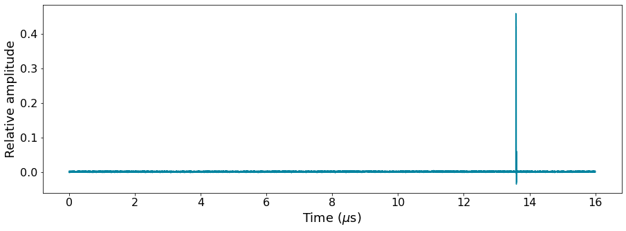
We start by running a trace acquisition to establish the threshold voltage at which we count a photon detection.
[ ]:
from quantify_scheduler.enums import BinMode
from quantify_scheduler.operations.gate_library import Measure

qe0.measure.pulse_amplitude(0.5)
qe0.measure.pulse_duration(16e-6)
qe0.measure.acq_duration(16e-6)
qe0.measure.acq_delay(0)


def trace_acquisition_sched(qubit: str, repetitions: int = 1) -> Schedule:
    schedule = Schedule("Trace Acquisition")
    schedule.add(Measure("qe0", acq_protocol="Trace"))
    return schedule


trace_schedule = trace_acquisition_sched("qe0")
compiler = SerialCompiler("compiler")
compiled_trace_sched = compiler.compile(trace_schedule, nv_center.generate_compilation_config())

compiled_trace_sched.plot_pulse_diagram(plot_backend="plotly")
[ ]:
ic.prepare(compiled_trace_sched)
ic.start()
data = ic.retrieve_acquisition()
ic.stop()
trace = data[0].real[0]
time = np.arange(0, 16000, 1)
[ ]:
fig, ax = plt.subplots(1, 1)
ax.plot(time / 1000, trace, color="#00839F")
ax.set_xlabel(r"Time ($\mu$s)")
ax.set_ylabel("Relative amplitude")

plt.show()
TTL Acquisition#
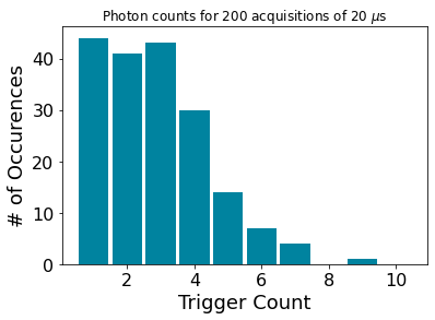
We can now set a correct threshold for the Trigger Count acquisition to ensure all the photon arrivals are counted a single time.
[ ]:
hardware_cfg = set_hardware_config(ttl_acq_threshold=0.3)
nv_center.hardware_config.set(hardware_cfg)

qe0.measure.pulse_duration(20e-6)
qe0.measure.acq_duration(20e-6)


def ttl_acquisition_sched(qubit: str, repetitions: int = 1):
    schedule = Schedule("TTL Acquisition")
    schedule.add(Measure("qe0", acq_protocol="TriggerCount"))
    schedule.repetitions = repetitions
    return schedule


schedule = ttl_acquisition_sched("qe0")
compiled_sched = compiler.compile(schedule, nv_center.generate_compilation_config())

compiled_sched.plot_pulse_diagram(plot_backend="plotly")
[ ]:
sched_kwargs = {
    "qubit": "qe0",
}

ttl_acquisition_gettable = ScheduleGettable(
    quantum_device=nv_center,
    schedule_function=ttl_acquisition_sched,
    schedule_kwargs=sched_kwargs,
    batched=True,
    data_labels=["Trigger Count"],
)
ttl_acquisition_gettable.unit = [""]
[ ]:
result = ttl_acquisition_gettable.get()
print("Photons counted: " + str(result[0][0]))
[ ]:
rep_par = ManualParameter(
    name="repetitions",
    unit="",
    label="Repetitions",
)
rep_par.batched = True
repetitions = 200
meas_ctrl.settables(rep_par)
meas_ctrl.setpoints(np.asarray(range(repetitions)))
meas_ctrl.gettables(ttl_acquisition_gettable)
dataset = meas_ctrl.run()
[ ]:
photon_count = dataset.y0

plt.hist(photon_count, bins=range(1, 10), align="left", rwidth=0.9, color="#00839F")
plt.title(r"Photon counts for 200 acquisitions of 20 $\mu$s")
plt.xlabel("Trigger Count")
plt.ylabel("# of Occurences")
plt.show()
Quantify - NV Center Native Library#
We define a schedule consisting of a Charge Reset operation which sets the NV to its negative charge state NV\(^-\), followed by a Charge and Resonance Count operation which runs the ionization and the spin pump lasers with a photon count, on the element qe0. These operations are defined in quantify_scheduler.operations.nv_native_library.
[ ]:
from quantify_scheduler.operations.nv_native_library import ChargeReset, CRCount

qe0.clock_freqs.ionization.set(564e12)  # 532 nm
qe0.clock_freqs.ge1.set(470.4e12 - 5e9)  # slightly detuned
qe0.clock_freqs.f01.set(3.592e9)
qe0.clock_freqs.spec.set(2.895e9)
[ ]:
# Define ChargeReset parameters
green_voltage = 0.697  # 30 uW

qe0.charge_reset.amplitude(green_voltage)
qe0.charge_reset.duration(40e-6)
[ ]:
# Define CRCount parameters
readout_voltage = 0.5
spinpump_voltage = 0.15

qe0.cr_count.readout_pulse_amplitude(readout_voltage)
qe0.cr_count.spinpump_pulse_amplitude(spinpump_voltage)
qe0.cr_count.acq_delay(5e-6)
qe0.cr_count.acq_duration(40e-6)
qe0.cr_count.readout_pulse_duration(45e-6)
qe0.cr_count.spinpump_pulse_duration(45e-6)
For this schedule, three lasers are used, as well as the other modules in the cluster. Since these are not present in the hardware configuration defined above, a new hardware configuration listing all the hardware is necessary. We load an example json hardware configuration file present in quantify_scheduler, which contains all the instruments required. Additionally, these are added to the instrument coordinator.
[ ]:
lo_spinpump_laser = find_or_create_instrument(
    MockLocalOscillator, recreate=True, name="lo_spinpump_laser"
)
lo_green_laser = find_or_create_instrument(
    MockLocalOscillator, recreate=True, name="lo_green_laser"
)

ic.add_component(GenericInstrumentCoordinatorComponent(lo_spinpump_laser))
ic.add_component(GenericInstrumentCoordinatorComponent(lo_green_laser))
[ ]:
# Define Schedule
def nv_schedule(qubit: str, repetitions: int = 1):
    sched = Schedule("NV Center Schedule")
    sched.add(ChargeReset(qubit))
    sched.add(CRCount(qubit, acq_index=0, acq_protocol="TriggerCount", bin_mode=BinMode.APPEND))
    return sched


compiled_nv_sched = compiler.compile(nv_schedule("qe0"), nv_center.generate_compilation_config())
compiled_nv_sched.plot_pulse_diagram(plot_backend="plotly")
compiled_nv_sched.plot_circuit_diagram()
[ ]:
sched_kwargs = {
    "qubit": "qe0",
}

nv_gettable = ScheduleGettable(
    quantum_device=nv_center,
    schedule_function=nv_schedule,
    schedule_kwargs=sched_kwargs,
    batched=True,
    data_labels=["Trigger Count"],
)
nv_gettable.unit = [""]
[ ]:
result = nv_gettable.get()
print("Photons counted: " + str(result[0][0]))
Dark ESR Schedule#
We turn now to the dark electron spin resonance (ESR) experiment. A predefined schedule has been defined in the Quantify Scheduler library, which uses the numerically controled oscillator frequency sweeping capabilities (see NCO Control tutorial for more information) to perform the spectroscopy operation in a defined frequency range. To ensure the NV center is in the correct state, after the Reset operation, a Charge Resonance check is performed before and after each Measure operation.
[ ]:
# Reset Operation
spinpump_reset_voltage = 0.502  # 0.5 uW
qe0.reset.amplitude(spinpump_reset_voltage)
qe0.reset.duration(3e-6)
[ ]:
# Spectroscopy Operation
qe0.spectroscopy_operation.amplitude(0.25)
qe0.spectroscopy_operation.duration(3e-6)
[ ]:
from quantify_scheduler.schedules.spectroscopy_schedules import nv_dark_esr_sched_nco

spec_frequencies = np.asarray(np.linspace(2.898e9, 3.098e9, 20))

compiler = SerialCompiler("compiler")
compiled_nv_sched = compiler.compile(
    schedule=nv_dark_esr_sched_nco("qe0", spec_clock="qe0.spec", spec_frequencies=spec_frequencies),
    config=nv_center.generate_compilation_config(),
)
[ ]:
schedule_kwargs = {
    "qubit": "qe0",
    "spec_clock": "qe0.spec",
    "spec_frequencies": spec_frequencies,
}

dark_esr_gettable = ScheduleGettable(
    quantum_device=nv_center,
    schedule_function=nv_dark_esr_sched_nco,
    schedule_kwargs=schedule_kwargs,
    batched=True,
    data_labels=["Trigger Count"],
)
dark_esr_gettable.unit = [""]
[ ]:
acq_par = ManualParameter(
    name="acq_index",
    unit="",
    label="Acquisition Index",
)
acq_par.batched = True
[ ]:
meas_ctrl.settables([acq_par, qe0.clock_freqs.spec])
meas_ctrl.setpoints_grid([np.asarray([0, 1, 2]), spec_frequencies])
meas_ctrl.gettables(dark_esr_gettable)
dataset = meas_ctrl.run()
[ ]:
rep_par = ManualParameter(
    name="repetitions",
    unit="",
    label="Repetitions",
)
rep_par.batched = True
[ ]:
repetitions = 10

meas_ctrl.settables([acq_par, rep_par, qe0.clock_freqs.spec])
meas_ctrl.setpoints_grid([np.asarray([0, 1, 2]), np.asarray(range(repetitions)), spec_frequencies])
meas_ctrl.gettables(dark_esr_gettable)
dataset = meas_ctrl.run()

