Cluster#
Throughout this documentation, the management module CMM is considered a mandatory component of the Mainframe. For clarity, the combination of the Mainframe and the CMM will be referred to as a single entity called a Cluster.
Description#
In this section, we have a look at the Qblox cluster mainframe, the CMM and their I/O.
Mainframe Front#
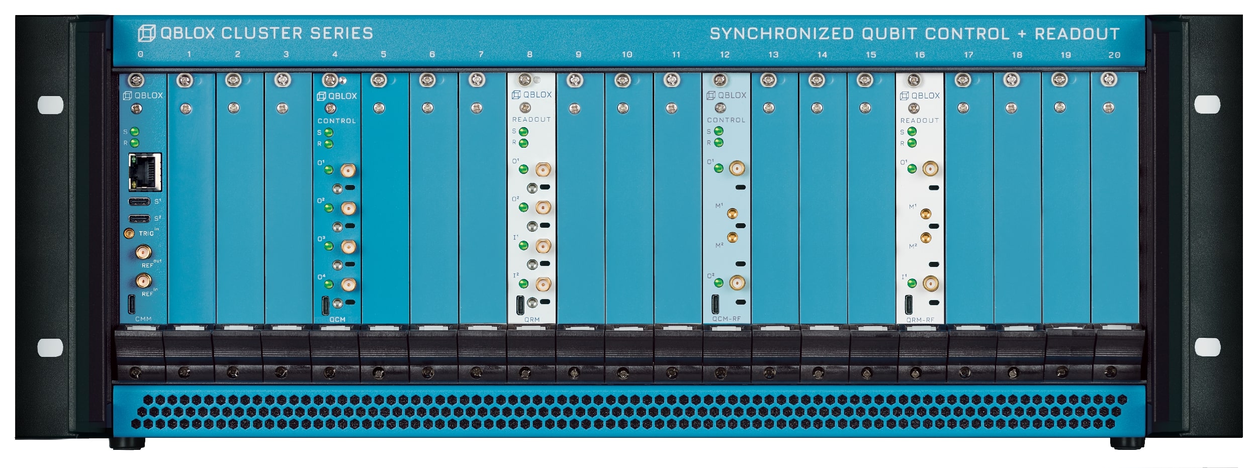
CMM module: present in every Cluster in slot 0, it allows communication from and to the host PC via Ethernet and the other modules. See more below.
20× module slots: each can be occupied by any module among QCM, QCM-RF II, QRM, QRM-RF or it can be left unoccupied. New modules can be added at any time when the cluster is switched off as the quantum device scales.
Mainframe Back#
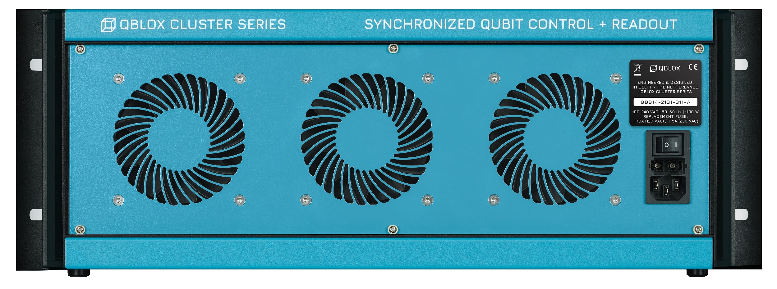
Power supply: 100–240 VAC, 50–60 Hz, 1100W.
Switch on/off.
3× cooling fans with dynamic fan control to minimize noise and keep a stable internal temperature.
CMM module#
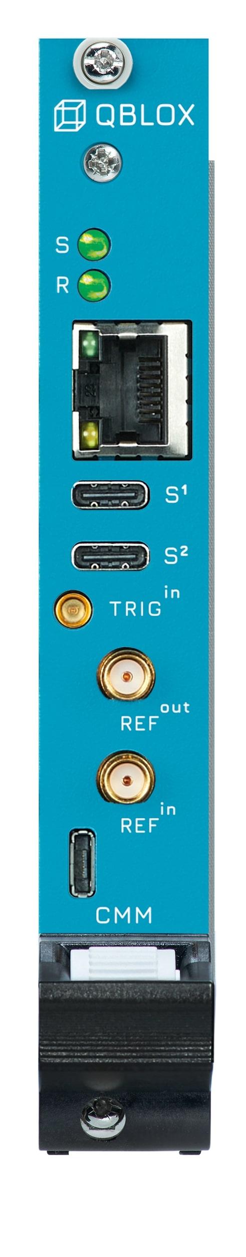
2 status LEDs: See section Frontpanel LEDs for details.
RJ45: 1 Gbps Ethernet host PC connection.
2 USB-C:
2 SYNQ: For synchronizing modules in multiple Qblox instruments.
1 SMP:
TRIG \(^\mathrm{\mathbf{in}}\) External trigger input (0–3.3 V, high-Z).
2 SMA:
REF \(^\mathrm{\mathbf{in}}\) External 10 MHz reference clock input (1 Vpp nominal @ 50 Ω).
REF \(^\mathrm{\mathbf{out}}\) 10 MHz reference clock output (0–3.3 V @ 50 Ω).
1 USB-micro:
UART/JTAG: For debug purposes only.
API and Communications#
All Qblox instruments, excluding the Mainframe, are controlled over Ethernet. They also all use a Python driver based on QCoDeS. Consequently, We recommend using this driver as it provides easy and clear access to all functionality of the instrument; even if you use a different lab framework as the overhead of QCoDeS is minimal.
SCPI Standard#
Underneath the QCoDeS driver layer, the control software is built upon the
SCPI standard, as also reflected in
API Reference. This means that all communication with the instrument happens using the
master/slave paradigm, where the host PC is the master and is always responsible for initiating communication by
issuing SCPI commands to the instrument. Of course, all of this is abstracted away at the driver level, so you don’t
have to have in-depth knowledge of the standard. However, if you are familiar with it, you will have access to all the
default SCPI functionality that you are used to, like qblox_instruments.native.Cluster.get_idn() (*IDN?),
qblox_instruments.Cluster.reset() (*RST) and qblox_instruments.scpi.Cluster.clear() (*CLS), albeit with
a slightly more readable name.
Tip
We advise resetting the instrument before starting your experiment to get the instrument into a well-defined state,
thereby improving the reproducibility of the experiment. Resetting the instrument is easily achieved by calling
qblox_instruments.Cluster.reset(). This will reset the instrument status and configuration to the default values.
It will reset all SCPI registers, including any reported error. It will also clear all stored Q1ASM programs, waveforms,
and acquisitions.
There are many use cases where you want to store the instrument’s settings before resetting, for instance, to be able to easily reproduce an experiment. For this, we advise using the snapshot feature of QCoDeS.
Errors#
Instrument errors are reported using SCPI’s system error registers, which can be read using
qblox_instruments.scpi.Cluster.get_num_system_error() (SYSTem:ERRor:COUNt?) and
qblox_instruments.scpi.Cluster.get_system_error() (SYSTem:ERRor:NEXT?). However, as mentioned before, this is
all abstracted away at the driver level. This means that the errors are automatically read and reported to you using
exceptions. Any driver function can throw these exceptions and you need to make sure these are handled appropriately,
for instance by using try statements.
Status & Flags#
The status of the instrument conveys the general operational condition of the instrument. This is derived from multiple
internal components, like PLLs and temperature sensors. The instrument’s status is updated every millisecond and stored
in the standard SCPI registers. It can be queried through these registers [e.g. through
get_status_byte() (*STB?)], but a more convenient way of reading out the
general instrument status is calling get_system_status(). The instrument status
is persistent through the state critical, so a way to reset it is required. This can be simply done by calling the
clear() to clear the state or by completely resetting the instrument by calling
reset().
Status#
BOOTING— Instrument is booting.OKAY— Instrument is operational.CRITICAL— Instrument has encountered an error (see flags below), but it has been corrected.ERROR— Instrument has encountered an error (see flags below), which needs to be fixed urgently.
Flags#
CARRIER PLL UNLOCKED— No reference clock found.FPGA PLL UNLOCKED— No reference clock found.LO PLL UNLOCKED— No reference clock found (only for RF modules).FPGA TEMPERATURE OUT-OF-RANGE— FPGA temperature has surpassed 90 °C.CARRIER TEMPERATURE OUT-OF-RANGE— Carrier board temperature has surpassed 60 °C.AFE TEMPERATURE OUT-OF-RANGE— Analog frontend board temperature has surpassed 75 °C.LO TEMPERATURE OUT-OF-RANGE— Local oscillator board temperature has surpassed 90 °C.BACKPLANE TEMPERATURE OUT-OF-RANGE— Backplane board temperature has surpassed 70 °C (only for Cluster).
Frontpanel LEDs#
The LEDs on the front panel of the Qblox instruments are used as a visual indication of the Status & Flags of the instrument.
Indicator |
Color |
Meaning |
|---|---|---|
S |
White |
Okay and idle (no connections). |
Green |
Okay. |
|
Yellow |
Booting (other LEDs are off). |
|
Orange |
Critical. |
|
Red |
Error. |
|
R |
Green |
External reference clock selected. |
Blue |
Internal reference clock selected. |
|
Red |
No reference clock found. |
|
I/O |
Green |
Channel idle. |
Purple |
Sequencer connected to channel is armed. |
|
Blue |
Sequencer connected to channel is running. |
|
Red |
Sequencer connected to channel failed. |
|
Orange |
Output values are clipping. |
Specsheet#
Warning
In case the equipment is used in a manner not specified in this manual, the protection provided by the equipment may be impaired.
Power Rating#
Parameter |
Condition |
Min |
Typ |
Max |
|---|---|---|---|---|
Rated AC voltage |
90V |
265V |
||
Rated AC current |
\(V_{in} = 90V_{ac}\) |
13.6A |
||
Rated AC frequency |
47Hz |
50/60Hz |
63Hz |
|
Rated power |
1100W |
|||
Trigger input voltage range |
0.0V |
3.3V |
||
Reference input voltage range |
-4.4V |
4.4V |
||
Fuse |
\(V_{in} = 120V_{ac}\) |
10A, Time delayed |
||
Fuse |
\(V_{in} = 230V_{ac}\) |
5A, Time delayed |
Note
For voltages between 110 Volt and 230 Volt, the fuse rating can be linearly interpolated.
Digital Interface#
Parameter |
Description |
|---|---|
Host computer connection |
1 GbE, Lan/Ethernet, 1Gbit/s. |
SYNC port |
Connector for Qblox proprietary synchronization protocol over a USB-C type connector. |
The ethernet should always be connected with a shielded category 5 or 6 ethernet cable. For optimal performance, use the included Cat6 S/FTP cables or similar ones.
I/O#
Parameter |
Condition |
Min |
Typ |
Max |
|---|---|---|---|---|
External clock input impedance |
50Ω |
|||
External clock input frequency |
10MHz |
|||
Reference clock output impedance |
50Ω |
|||
Reference clock output amplitude |
High impedance load |
3.3V |
||
Reference clock output frequency |
10MHz |
|||
Trigger input impedance |
100kΩ |
|||
Trigger input voltage range |
0.0V |
3.3V |
||
Trigger input threshold level |
0.9V |
Dimensions#
Parameter |
Condition |
Min |
Typ |
Max |
|---|---|---|---|---|
Dimensions |
W x H x D |
482 x 176 x 474 mm |
||
19 x 6.9 x 18.7 in |
||||
Weight |
Empty Rack |
9.35 kg |
Absolute Maximum Ratings#
Warning
This section shows the absolute maximum ratings of the cluster. Operation beyond these values can damage the cluster and installed modules!
Intended use#
The devices are meant for indoor use. For questions or more details, please contact us here.
Environmental#
Parameter |
Value |
|---|---|
Storage temperature |
0 – 45 °C |
Operating temperature |
5 – 40 °C |
Max humidity |
80 % |
Max altitude |
2000 m |
IP rating |
IP 20 |
Other characteristics |
Pollution Degree 2 |
Overvoltage Category II |
Product Compliance Information#
Parameter |
Standard |
|---|---|
Certifications |
CE |
Safety standards |
EN 61010-1 |
EMC standards |
Immunity: EN 61326-1 (Basic Electromagnetic Environment) |
RoHS |
EN IEC 63000 |
Warning
This equipment is not intended for use in residential environments and may not provide adequate protection to radio reception in such environments.