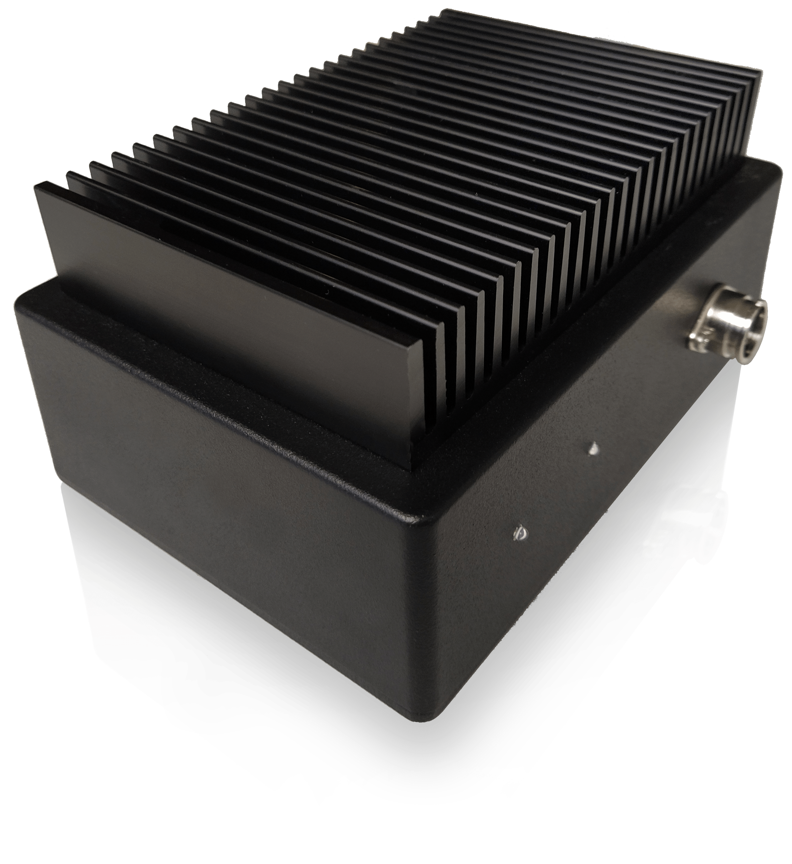
SPI mainframe & power supply#
Mainframe#
The SPI rack may house up to 12 modules in a modular chassis which connects the modules via an integrated backplane. The backplane provides digital communication and power to the modules through the C1b controller module, which establishes a connection between the SPI rack and the user PC.
With the C1b controller required for communication, up to 11 D5a or S4g modules can be installed. The C1b controller module is always slotted in the leftmost slot inside the chassis.
The internal backplane provides the following connections:
SPI Bus — Handles digital communication between all modules.
Digital lines — Used to trigger multiple modules at the same time.
Power supply — Supplies power to the modules.
The back of the SPI rack chassis hosts two sets of power connections:
Left-hand side: connections between the chassis and batteries.
Right-hand side: optional ±12 V and user-defined voltage connections (limited to AC ≤ 24 V, DC ≤ ±24 V, current ≤ 1 A).
Important
In a single SPI rack chassis, the maximum number of S4g modules operating at maximum rating is 5 modules. If a rack houses more than 5 S4g modules (up to 9 S4g modules), setup differences are required to ensure proper operation. Please see Setup with more than 5 S4gs units for details.
Mainframe Technical Specifications#
Environmental characteristics#
Environmental characteristics |
Values |
|---|---|
Max humidity |
80% |
IP Rating |
IP 20 |
IK Rating |
IK 08 |
Product Input#
Input Voltage (Gyrator) |
12 Vdc – 13.5 Vdc |
Input Voltage (SPI rack chassis) |
±6 Vdc |
Product Compliance#
Certifications |
|
CE |
|
Safety standard |
EN 6101-1 |
EMC Standards |
Immunity: EN 61326-1 (Basic Electromagnetic Environment) Emission: EN 61326-1 EN 55011 (Class A)* EN 61000-3-2 (Class A) EN 61000-3-3 Caution: This equipment is not intended for use in residential environments and may not provide adequate protection to radio reception in such environments. |
RoHS |
EN IEC 63000 |
FCC |
|
Standard |
FCC Part 15* (Class B) Changes or modifications not expressly approved by the party responsible for compliance could void the user’s authority to operate the equipment. Note: This equipment has been tested and found to comply with the limits for a Class B digital device, pursuant to part 15 of the FCC Rules. These limits are designed to provide reasonable protection against harmful interference in a residential installation. This equipment generates, uses and can radiate radio frequency energy and, if not installed and used in accordance with the instructions, may cause harmful interference to radio communications. However, there is no guarantee that interferenc…
|
Power chain#
The power chain in the SPI setup consists of an external power supply unit (PSU), the gyrator, and the battery unit. Together they are isolated from the SPI rack chassis — ideal for sensitive DC measurements.
External Power Supply unit#
The PSU is an external linear AC/DC supply providing a constant voltage. In combination with the gyrator, it prevents ground loops and interference.
Important
The PSU must meet the specifications in the table below. Exceeding these requirements can damage components or result in insufficient power.
External Power Supply Characteristics |
||
|---|---|---|
Input |
240 Vac |
|
Output |
2 outputs |
|
12–13.5 Vdc / output |
||
2 A / output |
||
Type |
Linear Power Supply |
Switched-mode PSUs generally introduce too much noise and lack ground-loop isolation, making them unsuitable. |
Required standards |
Safety: IEC/EN 61010-1 |
EMC: IEC/EN 61326-1 (Emission: Class B, Immunity: Basic Electromagnetic Environment) |
Gyrator#
The gyrator contains a common-mode choke and active circuitry, mimicking a large inductor (40 H) on every power lead. It prevents interference signals above 50 Hz from reaching the SPI rack, since there are no physical connections between mains ground and the SPI rack.

Battery unit#
The battery unit consists of two batteries, each containing two 6 V lead-acid batteries (12 Ah total) in a metal box. Fuses prevent excessive currents (>6 A) in case of a short circuit.
The battery type used in the enclosure can be seen here.