QSM#
Description#
The Quantum Source and Measurement (QSM) module is Qblox’s integrated solution for DC transport and characterization. Designed specifically for the DC Cluster, the QSM is capable of sourcing voltage and current, and measuring current. The module features eight DC I/O channels with a 28-bit resolution over a ±10 V range (step size of less than 0.6 µV). The front panel is equipped with eight SMP male pins and the QSM I/O operational status are continuously monitored by four LED lights.
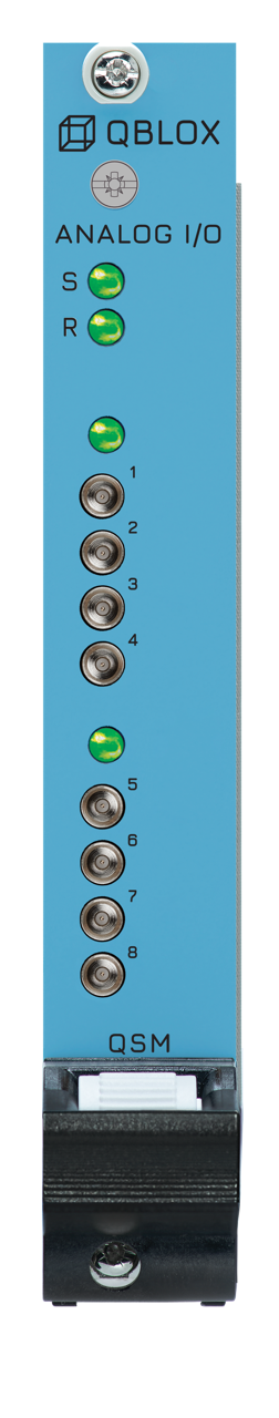
On the front of a QSM module you will find the following components:
8 x SMP male (pin) connectors: 8 I/O ±10 V range.
4 x status LEDs: See section Frontpanel LEDs for details.
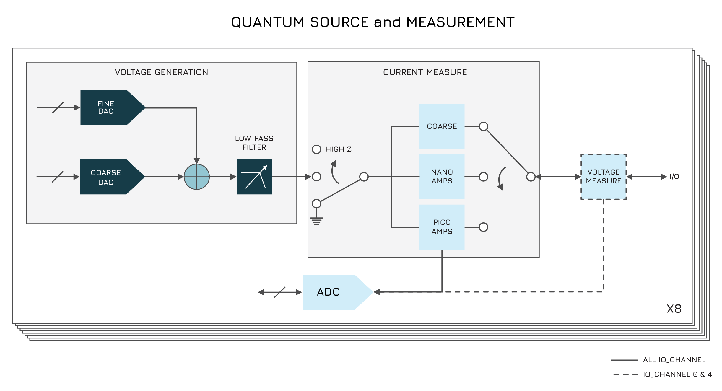
The module combines wide-range biasing with high-resolution current readout, enabling precise control of device operating points during DC transport experiments or qubit experiments. Each channel integrates coarse and fine DACs, selectable output filtering, and an internal switch-to-ground for rapid isolation. Current can be monitored simultaneously across all channels with sub-picoampere resolution. All sourcing and measurement functions are accessed through the QCoDeS-based Qblox Instruments API, providing safe ramping, value validation, and hardware-level fail-safes built into the DC Cluster architecture. See details on features below.
Block Diagram#
Features#
Driver Included#
Control is provided through the Qblox Instrument package (QCoDeS-based), using SCPI commands over Ethernet (1 Gbit/s) for deterministic and high-bandwidth communication. For more details, explore the complete QSM API.
Sourcing#
The QSM is capable of sourcing both voltage and current from the IO channels.
Tip
The module requires a warm-up period. We recommend allowing at least one hour of warm-up time to achieve optimal output stability.
Note
QSM can also be operated in a Cluster at the cost of losing the ground loop isolation and potentially increasing noise at the output.
Warning
The nominal current limit per output is 50 mA. Integrated protection circuitry prevents damage by blocking output levels that would exceed this threshold.
Voltage sourcing#
Voltage sourcing is implemented through a dual-DAC design on each output:
Coarse DAC: ±10 V range, 20-bit resolution (
IOChannel.coarse_voltage()).Fine DAC: 0–2.5 mV range, 16-bit resolution (
IOChannel.fine_voltage()).
Both DACs operate independently, enabling wide-range biasing with an effective 28-bit trimming.
Additionally, an internal switch-to-ground can be activated at any time by setting IOChannel.source_mode() to
ground, providing immediate isolation from the device.
Current sourcing#
Added in version 2026.07.0: See the release notes for details.
For current sourcing, the DACs are utilized to allow sourcing current directly through a static or changing load.
Sourcing the current is done through IOChannel.set_current_wait(), which sets the given current as argument and
waits until the given current has been reached. The user is allowed to source current between -50 mA to +50 mA. Prior to
sourcing the current, ensure that the source_mode for the given IOChannel is set to i_source to allow current to
be sourced. Additionally, the range of the allowed sourced current can also be set via
IOChannel.set_safe_current_range(). This will ensure that the sourced current can not exceed the given range for
your measurements.
Measurement#
Current on all outputs can be monitored simultaneously at 250 Ks/s with three selectable resolution levels via
IOChannel.measure_mode() :
Coarse: ±50 mA range (
Coarse).Nano ampere resolution ±10 μA range (
fine_nanoampere).Pico ampere resolution ±10 nA range (
fine_picoampere).
The different resolutions allow measurements down to picoampere current. This precision enables precise tracking of leakage, drift, or device turn-on behavior while biasing sensitive structures such as quantum dots or transistors.
For the current measurement mode, the integration time (IOChannel.integration_time()) is adjustable from 20 μs up
to 1 s.
Warning
A short circuit on the output, combined with coarse current mode, will result in a current draw exceeding the specified 50 mA limit. If this condition occurs on all channels simultaneously, it might cause damage.
Analogue filters & output impedance#
Each I/O channel includes selectable low-pass filtering (IOChannel.low_pass_filter_cutoff()) with cutoff
frequencies of 10 Hz, 10 kHz and 250 kHz. The output impedance is 2 Ω for all filter configurations, ensuring
predictable loading behavior regardless of the selected bandwidth.
Important
Whenever you want to set the IOChannel.low_pass_filter_cutoff(), you need to ensure that the source_mode is set to ground prior.
Once the cutoff filter is set, the source mode can be changed to the desired source mode needed for your experiment.
Security#
DC stability and reliability is paramount for device safety. The QSM and DC cluster mainframe offer multiple redundant safety features to prevent voltage peaks that could damage a device:
Device protection is ensured through:
Configurable slew rates to control voltage transitions and avoid overshoot (
IOChannel.slew_rate()).Configurable validators to reject unsupported or unsafe setpoints via the software such as negative values (
IOChannel.set_safe_voltage_range()).Ramp down switch (on the DC Cluster backplane) which ramps all outputs to 0 V and grounds them - fallback option if communication with the cluster is not possible.
Tip
This switch rests in the down position by default. Moving it to the up position grounds all system outputs. When the switch is already in the up position, returning the switch to the down position has no effect on the outputs.
Tips#
Warning
Switching between settings (current measurement circuit and filter) can cause small output voltage jumps.
Note
Fine current measurement output voltage can not be guaranteed when its outside of its range.
Absolute Maximum Ratings#
Warning
This section shows the absolute maximum ratings of the cluster QSM module. Operation beyond these values can damage the module and cluster!
Parameter |
Condition |
Min |
Typ |
Max |
|---|---|---|---|---|
Voltage applied to output |
-10V |
+10V |
||
Current applied to output |
-50mA |
+50mA |
||
Current applied to input |
-50mA |
+50mA |
Specifications#
Module#
Quantity |
Value |
|---|---|
Power consumption |
29 W (worst case scenario) |
Power supply |
Via DC Cluster |
Data connection to host PC |
1 Gbit/s via DC Cluster |
Driver / API |
SCPI / QCoDeS / Python |
Connector type |
SMP |
Dimensions (single module) |
269 × 130 × 20 mm³ |
Weight |
0.438 kg |
Outputs#
Quantity |
Value |
|---|---|
Voltage sourcing |
all channels |
Output voltage range |
±10 V |
DC resolution (effective) |
28 bits |
Output impedance |
2 Ω |
Output step size |
< 0.6 µV |
Selectable output filters |
10 Hz, 10 kHz, 250 kHz |
Current sourcing |
all channels |
Output compliant current |
±50 mA |
Rise time (0–1 V step) |
32 ms @ 10 Hz |
Temperature coefficient (output) |
0.05 ppm/°C of range + 0.45 ppm/°C of output |
Update time (voltage/current) |
2 ms |
1/f noise @ 100 Hz (10 V, 250 kHz filter) |
< 20 nV/√Hz |
Note
For temperature stability, the coefficient holds after the initial warmup of the module and with a stable fanspeed of the cluster.
Inputs#
Quantity |
Value |
|---|---|
Current measurement |
all channels |
Current measurement range |
0.5 pA to 50 mA |
Current measurement resolution |
0.5 pA @ 0.5 pA–10 nA |
Current measurement sample rate (1 nA–50 mA range) |
250 Ks/s |
Temperature coefficient (current) |
80 ppm/°C (pA range) |
Product Compliance Information#
Caution
This equipment is not intended for use in residential environments and may not provide adequate protection to radio reception.
Compliance is only guaranteed with cables up to 3m
Category |
Standard / Certification |
Notes |
|---|---|---|
Certification |
CE |
— |
Safety |
EN 61010-1 |
Safety requirements for electrical equipment |
EMC – Immunity |
EN 61326-1 (Basic Electromagnetic Environment) |
— |
EMC – Emissions |
EN 61326-1 |
*Class A: industrial environment |