QRC#
Description#
The Quantum Readout and Control (QRC) module is Qblox’s solution for academic and industrial partners aiming to support qubit scaling challenges. As its name suggests, this product is capable of both controlling and reading out qubits while covering a different frequency range than previous offerings. This module is the first in the Qblox lineup to use a direct digital synthesis (DDS) up-conversion scheme with single mixing between the Nyquist zones. This method ensures optimal signal quality at all times. The QRC module features six fully independent ports for signal generation, with a continuous frequency range from 100 MHz to 10 GHz, along with two input channels for readout. Additionally, the module comes with one SMP male pin for triggering. Its operational status is continuously monitored by eight LED lights. The front of a QRC module is presented below:
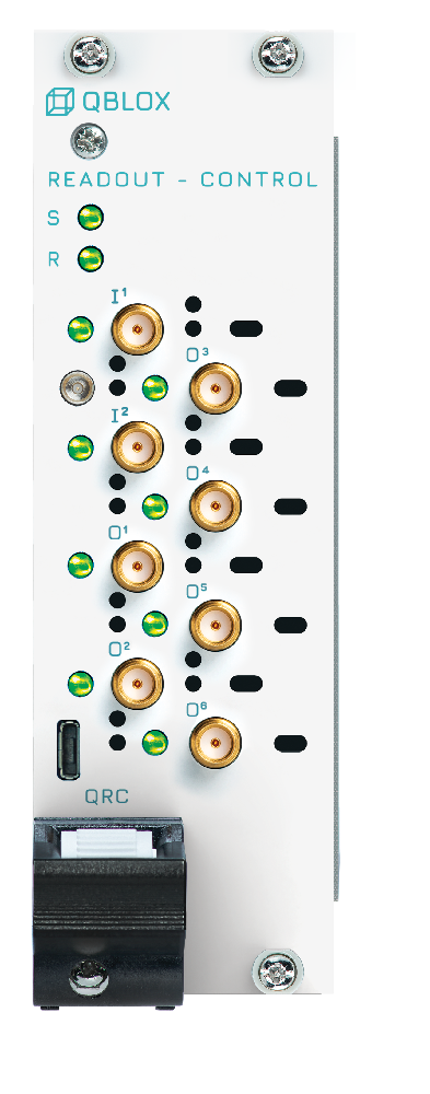
On the front of a QRC module you will find the following components:
8 x SMA female (receptacle) connectors: 6 output (O[1…6]: @ 50 Ω) ; and 2 input channels (I[1, 2]: @ 50 Ω).
1 x SMP male (pin) connector: Marker output channel (0-3.3 V TTL).
8 x status LEDs: See section Frontpanel LEDs.
The QRC module is designed to perform both qubit control and readout within a single instrument. The operation of the module is similar to other qblox modules, with 8 readout sequencers and 4 control sequencers onboard.
The module creates signals parametrized by variables such as gain, offset, NCO frequency and phase, etc., and also by waveform envelopes stored in memory. This parametrization is controlled by the AWG paths of the Q1 sequencer, which have two waveform paths each. The outputs of the AWG paths are mixed with the LO and NCO, enabling operation as modulated IQ signals. These paths can be connected to any output of the instrument (i.e. O1, O2,…, O6). The RF upconversion stage features a frequency plan utilizing both DDS and mixing for generating the output signals in the range of 0.1-10GHz.
Each readout sequencer can target one qubit for readout, allowing multiplexed readout of multiple qubits on the same channel. The AWG paths can generate the readout pulses and the acquisition paths can process the returned readout data. The acquisition path supports any combination of three acquisition modes:
Scope: Returns the raw input data.
Integration: Returns the result after integrating the input data; optionally based on an integration function stored in memory.
Thresholded: Returns the binary qubit value after thresholding the integrated value.
The results of the acquisitions are returned to the user through the qblox_instruments driver.
For a list of available features please go to Features
Block Diagram#
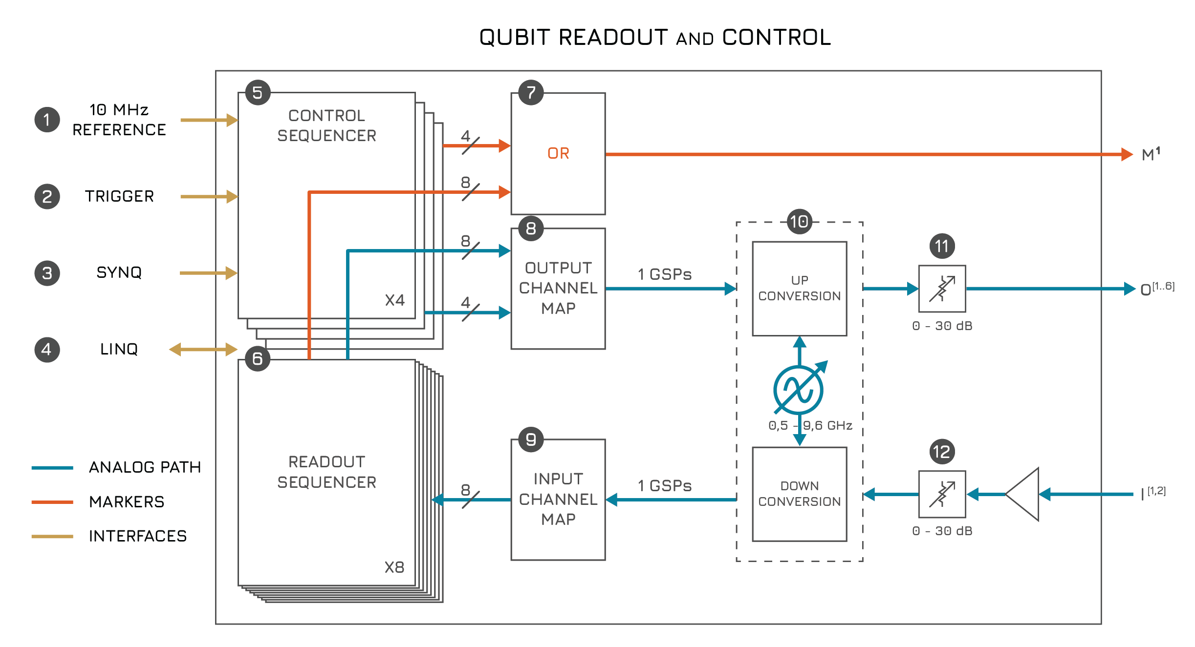
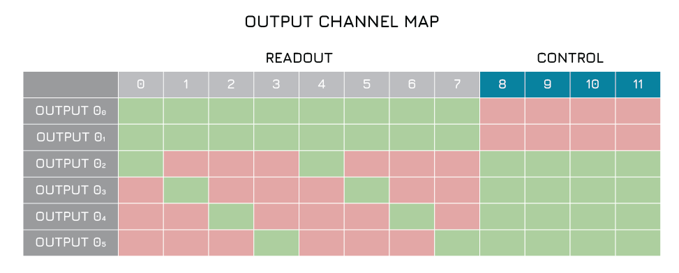
Block diagram of a Qubit Readout Control Module.#
Block diagram of a Qubit Readout Control Module.#
The QRC module contains the following features:
Features#
Notable differences to the RF modules
If you are familiar with the qblox QCM-RF and QRM-RF modules, keep the following differences in mind:
The QRC offers significantly higher input gain. To avoid overdriving the ADC you may need to change input attenuation settings.
The center frequency of the QRC is set in 100 MHz increments.
Cluster.reset()will take a few seconds longer to complete if one or more QRC modules are present.Since QRC features two input channels, the general acquisition data format has been expanded. The QRC returns data across four paths: path0 and path1 correspond to input1, while path2 and path3 correspond to input2.
1. 10MHz Reference#
Alongside all modules available, the QRC module operates with respect to a 10MHz reference provided by the cluster.
2. Trigger#
The QRC is connected to the internal trigger network of the cluster and allows for fast synchronization between modules.
3. SYNQ#
The Qblox SYNQ technology enables simple and quick synchronization over multiple instruments, allowing for modules to be started synchronously \(\ll 1ns\). See section synchronization for more information.
4. LINQ#
The Qblox LINQ technology allows for the results of measurements to be shared between devices, distributing outcomes in < 500 ns.
Sequencers#
The Q1 sequencers are the heart(s) of the QRC instrument. They orchestrate the experiment using a custom low-latency sequence processor specifically designed for quantum experiments.
The QRC features 8 sequencers capable of both readout and control of qubits, and 4 additional sequencers for qubit control.
5. Q1 Control Sequencer#
Each QRC has 4 control sequencers to target multiple qubits with one instrument.
Each control sequencer has a dedicated AWG path, which enables parametrized pulse generation.
6. Q1 Readout Sequencer#
Each QRC has 8 readout sequencers to target multiple qubits with one instrument.
Each control sequencer has a dedicated AWG and acquisition path, which enables parametrized pulse generation and readout.
7. Marker Output Channels#
Each sequencer has control over the marker output channel, with the control of each sequencer being OR’ed to create the
final marker output. The markers can be dynamically controlled with the set_mrk instruction of the sequence processor
(see section on latched instructions), but can also be
overwritten with the static marker overwrite parameters Sequencer.marker_ovr_en() and
Sequencer.marker_ovr_value(). The marker output range is 0-3.3 V TTL.
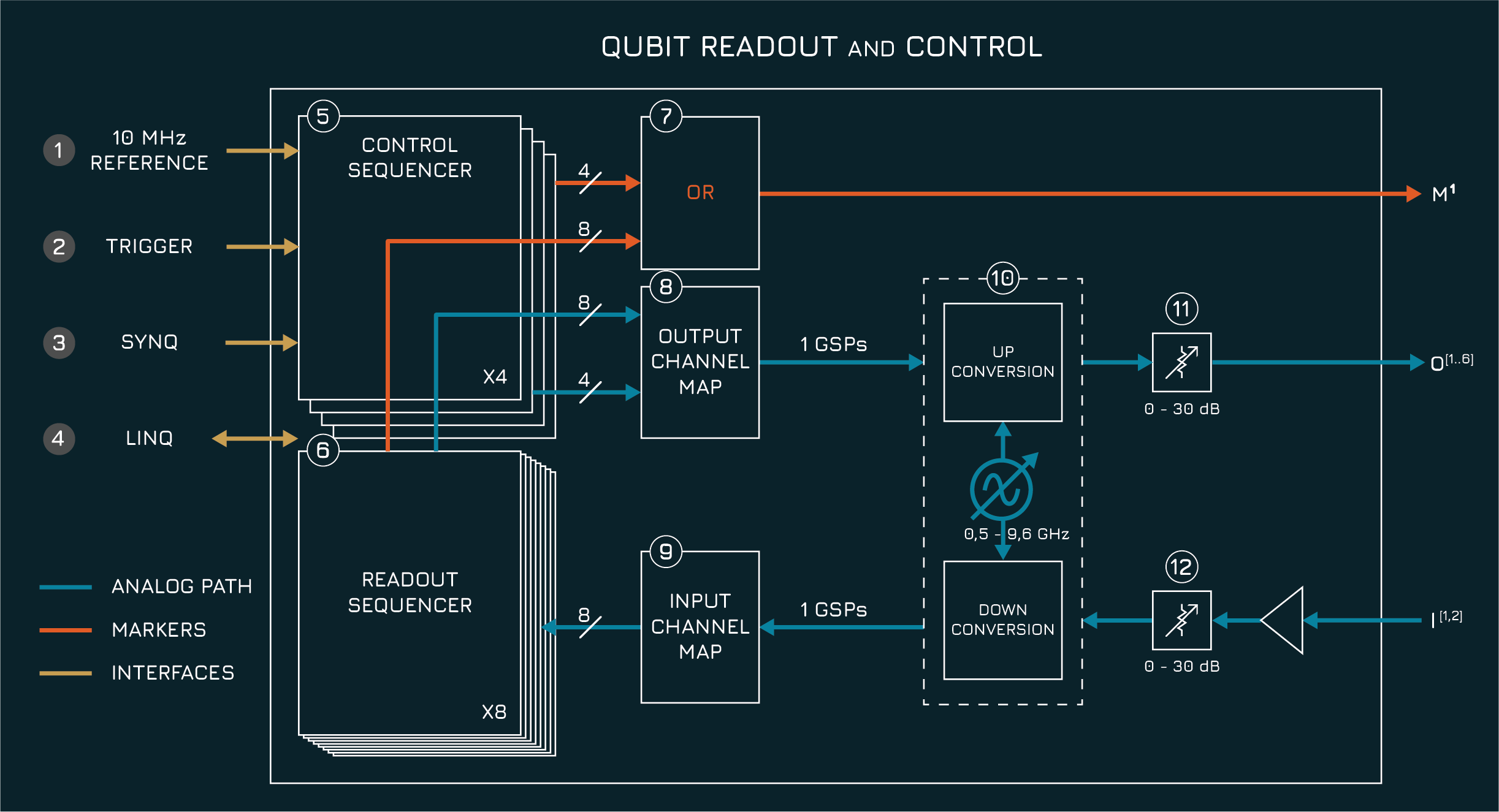
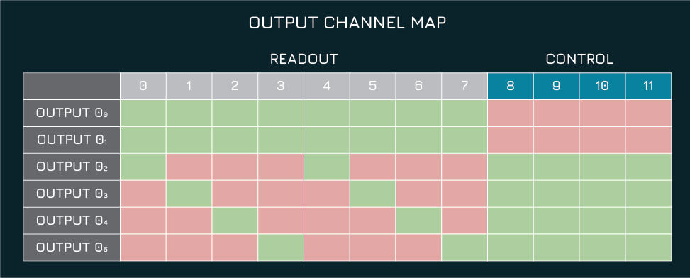
8. Output Channel Map#
Each of the 8 readout and 4 control sequencers in a QRC has one complex output stream. This can either be connected to or disconnected from one or more outputs using the channel map.
ControlSequencer.connect_out0()connects a sequencer output stream to output 0. For example, to connect the IQ path of sequencer 2 to output 1, useQRC.sequencer2.connect_out1("IQ"). The argument may be “IQ” (True) or “off” (False). All the output streams that are connected to the channel map are added together. This may result in clipping.
For more details about multiplexing and its operation on our cluster, please refer to the multiplexed sequencing tutorial.
The permitted mapping from sequencers to outputs is shown below:
Output channel map of a Qubit Readout Control Module.#
Output channel map of a Qubit Readout Control Module.#
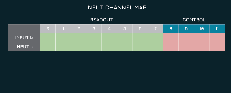
9. Input Channel Map#
Each of the 8 readout sequencers in a QRC has one complex input stream. This can either be connected to or disconnected from either input using the channel map.
ReadoutSequencer.connect_acq()connects an input to a sequencer path. For example, to connect input 1 to the IQ path of sequencer 2, useQRC.sequencer2.connect_acq("in1"). The argument may be “in0”, “in1” or “off”. All the sequencers whose input streams are connected to an input receive the same input samples.
For more details about multiplexing and its operation on our cluster, please refer to the multiplexed sequencing tutorial.
Note
The default state is that the input and output stream of all sequencers is connected to input0 and output0. This is so that the modules can always play a sequence in their default state.
Note
Since the QRC features two input channels, the general acquisition data format has been expanded. While the QRM-RF only returns data under path0 and path1 (representing its single input), the QRC returns data across four paths: path0 (I) and path1 (Q) correspond to input1, while path2 (I) and path3 (Q) correspond to input2.
The channel map may be cleared by setting all connect_out* and connect_acq_* parameters for all sequencers to ‘off’.
The QRC.disconnect_outputs() and QRC.disconnect_inputs() convenience functions may be used as shorthand.
The permitted mapping from sequencers to inputs is shown below:
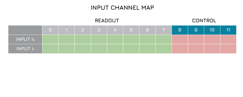
Input channel map of a Qubit Readout Control Module.#
Input channel map of a Qubit Readout Control Module.#
10. Up- and Downconversion stage#
The QRC module employs a hybrid oscillator and signal-generation architecture that combines direct digital synthesis (DDS) with a single-mixing stage to provide a calibration-free, continuous, gap-free frequency coverage from 100 MHz up to 10 GHz.
The sequencers of the QRC operate on a 1 ns time grid. The signal is digitally up/downconverted to the 5 GSa/s DAC/ADC.
Depending on the desired target frequency, signals are then either generated using DDS, benefiting from excellent frequency resolution, deterministic phase control, and low intrinsic phase noise. When other output frequencies are required, a carefully engineered single-mixing stage is engaged to convert the DDS output to the desired target frequency, ensuring that no spectral gaps occur across the full operating range. This approach is illustrated in the animation below.
The oscillator path selection and configuration are handled automatically by the hardware and firmware, allowing users
to specify a desired center frequency without manual intervention or recalibration, see QRC.out0_in0_lo_freq() and
QRC.out3_lo_freq(). This approach minimizes reliance on multiple high-frequency local oscillators, reducing system
complexity and phase-noise accumulation while maintaining a wide instantaneous bandwidth around the selected frequency.
Each channel operates independently, enabling flexible multi-frequency operation and precise phase-coherent control
suitable for advanced quantum readout and control applications.
Similar to the QRM-RF, the oscillator used for the mixing path is shared within each input-output pair, eliminating relative phase drifts between output and input. When using the DDS path, each input-output pair shares settings by default and is therefore phase deterministic.
Illustration of the frequency plan of the QRC. Depending on the desired frequency range, the module will automatically choose between direct digital synthesis and a mixer path. Analog filter bands are automatically set to remove the undesired sidebands, allowing calibration-free operation.#
11. Variable Output Attenuator#
The QRC module has a variable output attenuator, which can be programmed. The maximum value of the variable attenuation depends on frequency, but is at least 15 dB. The output attenuation can be programmed to be between 0 to and the maximum in 0.5 dB steps.
12. Variable Input Attenuator#
Tip
The QRC features significant input amplification. Without input attenuation set, the ADC may start clipping already at -45 dBm input power. This means that it may be necessary to set the input attenuation to maximum in a loopback configuration to avoid clipping.
The QRC module has a variable input attenuator, which can be programmed. The maximum value of the variable attenuation depends on frequency, but is at least 40 dB. The output attenuation can be programmed to be between 0 to and the maximum in 0.5 dB steps.
Absolute Maximum Ratings#
Warning
This section shows the absolute maximum ratings of the cluster QRC module. Operation beyond these values can damage the module and cluster!
Output#
Parameter |
Max |
|---|---|
Max Torque |
45 Ncm |
Input#
Parameter |
Max |
|---|---|
Input Power |
20 dBm |
Max Torque |
45 Ncm |
Specifications#
Module#
Parameter |
Value |
|---|---|
Dimensions |
269x130x40 \(mm^3\) |
Output#
Parameter |
Condition |
Min |
Typ |
Max |
|---|---|---|---|---|
Number of channels |
6 |
|||
Carrier frequencies per channel |
8 |
|||
Output coupling |
AC |
|||
DAC dynamic range |
14bits |
|||
DAC sample rate |
5GS/s |
|||
Mute switch isolation |
50 dB |
|||
Output impedance |
50Ω |
|||
Output power |
In 50Ω load |
5dBm |
||
Variable attenuator range |
Depends on frequency |
15dB |
Input#
Parameter |
Condition |
Min |
Typ |
Max |
|---|---|---|---|---|
Number of channels |
2 |
|||
Carrier frequencies per channel |
8 |
|||
Input coupling |
AC |
|||
ADC dynamic range |
15bits |
|||
Input impedance |
50Ω |
|||
Input power |
At full ADC range |
-45dBm |
6dBm |
|
Variable attenuator range |
Depends on frequency |
40dB |
50dB |
Marker Outputs#
Parameter |
Condition |
Min |
Typ |
Max |
|---|---|---|---|---|
Number of markers |
1 |
|||
High voltage |
high Z load |
3.3V |
||
Low voltage |
0.0V |
Typical Performance#
Output#
Parameter |
Condition |
Min |
Typ |
Max |
|---|---|---|---|---|
Output frequency range |
0.1GHz |
10GHz |
||
Analog bandwidth |
800MHz |
|||
Phase noise |
10kHz offset at 6 GHz |
-108 dBc/Hz |
||
Carrier to noise density \(C/N_0\) |
Across entire frequency range |
150 dB-Hz |
||
Mute switch isolation |
50 dB |
Input#
Parameter |
Condition |
Min |
Typ |
Max |
|---|---|---|---|---|
Input frequency range |
0.1GHz |
10GHz |
||
Analog bandwidth |
800MHz |
Product Compliance Information#
Compliance with EMC requirements is only guaranteed with cables up to 30 meters.