

See also
A Jupyter notebook version of this tutorial can be downloaded here.
Real-Time Coulomb Peak Tracking simulator#
This tutorial demonstrates the Qblox Cluster’s capability to autonomously re-tune quantum dot charge sensors at high speeds. By leveraging integrated FPGA processing and low-latency feedback, the system can maintain optimal readout points in real-time, significantly reducing the overhead of manual re-calibration. More information on the real-time feedback capabilities can be found on the LINQ-based feedback feature page.
Motivation#
In spin qubit experiments, a charge sensor (a single electron transistor or a quantum point contact) is used to sense the nearby spin qubit. To achieve maximum readout fidelity, the sensor must be precisely tuned to its most sensitive region (the point as which the gradient of the Coulomb peak is maximum), often referred to as the “sweet spot”.
However, quantum devices frequently suffer from environmental drift, causing the Coulomb peak to shift and requiring constant re-tuning. This tutorial shows how to use the fast real-time feedback to track and adjust the peak automatically.
Disclaimer: This is a simulator. This shows the proof of concept of the Coulomb peak tracker, but it cannot tune the physical quantum dot.
Implementation Strategy#
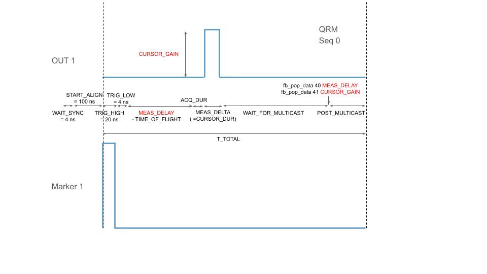
Peak Generation: The Qubit Control Module (QCM) generates a simulated Coulomb peak.
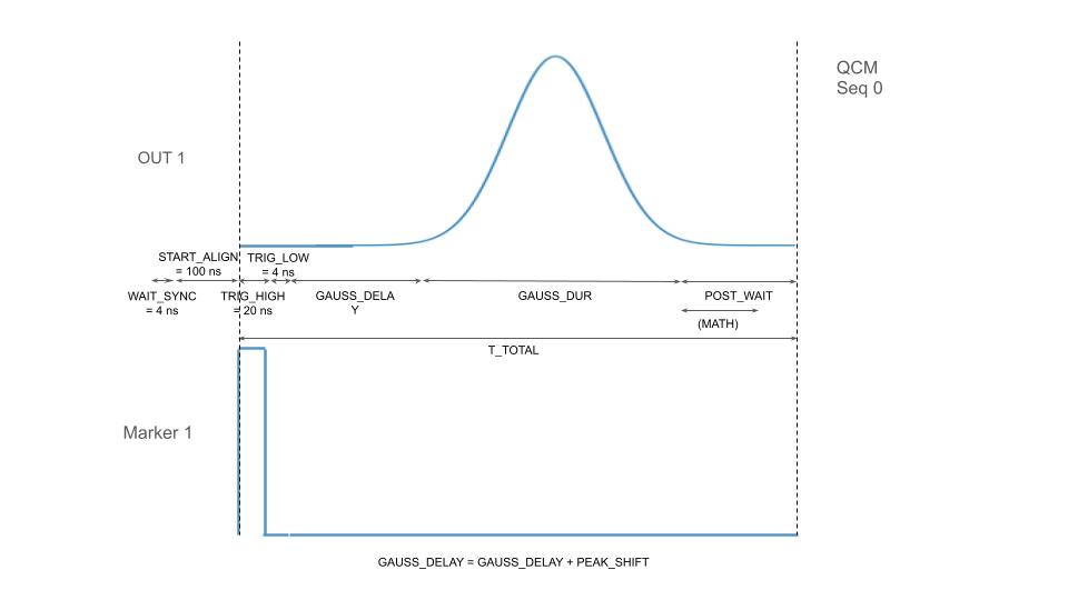
Measurement Cursor: The Qubit Readout Module (QRM) outputs a cursor (a square pulse) at a specific measurement position and acquires the signal. Note: The purpose of this cursor is to allow for visual tracking and is not strictly necessary for implementation.
Gradient Calculation: The QRM measures the peak amplitude twice around the cursor (at the rising and falling edges). The QCM receives the measurement and calculates the gradient.
Active Tracking: The QCM constantly compares the measured gradient to its neighbor. The QCM and QRM updates their delay and gain parameters to reach the sweet spot.
Random Drift: We provide an artificial drift by a random amount, to demonstrate that the active tracking tracks and locks on the new sweet spot.
Imports
[1]:
from __future__ import annotations

import json

import numpy as np
import scipy.signal
from qcodes.instrument import find_or_create_instrument

from qblox_instruments import Cluster, ClusterType
Define the meausrement instruments. For this tutorial, we need a Cluster equipped with a QCM and a QRM.
[2]:
cluster_ip = None
cluster_name = "cluster0"

cluster: Cluster = find_or_create_instrument(
    Cluster,
    recreate=True,
    name=cluster_name,
    identifier=cluster_ip,
    dummy_cfg=(
        {
            2: ClusterType.CLUSTER_QCM,
            4: ClusterType.CLUSTER_QRM,
            6: ClusterType.CLUSTER_QCM_RF,
            8: ClusterType.CLUSTER_QRM_RF,
            10: ClusterType.CLUSTER_QTM,
            12: ClusterType.CLUSTER_QRC,
            16: ClusterType.CLUSTER_QSM,
        }
        if cluster_ip is None
        else None
    ),
)

cluster.reset()
print(cluster.get_system_status())
Status: RESOLVED, Flags: TEMPERATURE_OUT_OF_RANGE, Slot flags: SLOT2_TEMPERATURE_OUT_OF_RANGE, SLOT4_TEMPERATURE_OUT_OF_RANGE, SLOT6_TEMPERATURE_OUT_OF_RANGE, SLOT8_TEMPERATURE_OUT_OF_RANGE, SLOT10_TEMPERATURE_OUT_OF_RANGE, SLOT12_TEMPERATURE_OUT_OF_RANGE, SLOT16_TEMPERATURE_OUT_OF_RANGE
[3]:
qcm_modules = cluster.get_connected_modules(lambda mod: mod.is_qcm_type and not mod.is_rf_type)
qcm_module = list(qcm_modules.values())[0]
qrm_modules = cluster.get_connected_modules(lambda mod: mod.is_qrm_type and not mod.is_rf_type)
qrm_module = list(qrm_modules.values())[0]
Hardware Setup#
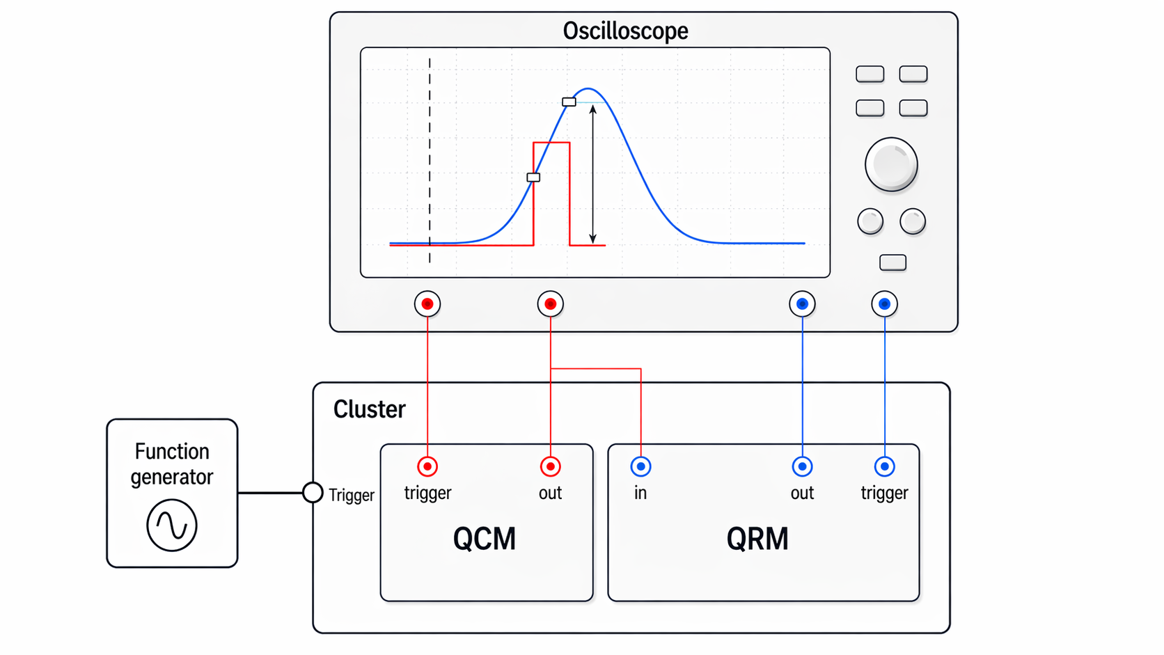
As can be observed from the experimental setup shown above, the relevant instruments, modules, and connections for this tutorial are:
Function generator:
Provides the external trigger signal to the Cluster.
Cluster:
Receives the external trigger from the function generator.
Hosts the QCM and QRM modules used in this setup.
QCM:
trigger: Trigger-related signal line monitored on the oscilloscope.out: Output signal line connected to the oscilloscope.The
outline is also routed to the QRMin.
QRM:
in: Input line connected to the QCMout.out: Output signal line connected to the oscilloscope.trigger: Trigger-related signal line connected to the oscilloscope.
Oscilloscope:
One channel is connected to the QCM
trigger.One channel is connected to the QCM
out.One channel is connected to the QRM
out.One channel is connected to the QRM
trigger.
Sequencer Synchronization: Four Sequencers Talking to Each Other#
Multiple sequencers across different modules (QCM and QRM) can share real-time data with extremely low latency (~500 ns) over the CMM backplane. We synchronize all four sequencers together so that the generated signals and the readout acquisitions align in time. These Q1ASM instructions are saved in four separate files, each file contains the commands for one sequencer.
This interactive timeline can help your understanding.
Peak generation with artificial drift with a pseudo-random generator#
The QCM sequencer 0 generates a simulated Coulomb peak. To prove that our active tracking works against unpredictable environmental noise, we simulate physical drift. Instead of pre-calculating this drift on the computer, we utilize a Pseudo-Random Number Generator (PRNG) implemented using Q1ASM instructions. See qcm_seq0.q1asm for more details.
QRM measure and cursor#
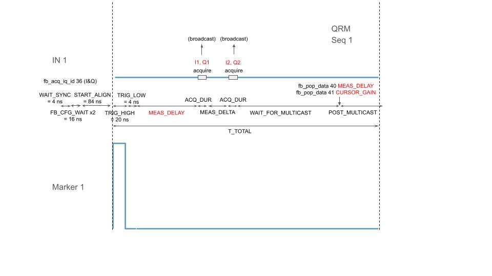
Updates MEAS_DELAY and CURSOR_GAIN according to the measurement taken. The parameters are updated directly on the FPGA. See qrm_seq0.q1asm and qrm_seq1.q1asm for more details.
“QCM Brain”: calculates gradients and finds the sweet spot#
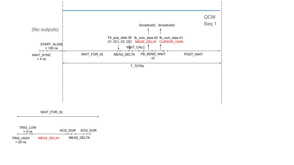
QCM sequencer 1 finds the “sweet spot” of the Coulomb peak, which requires calculating gradients. Rather than sending data back to the host PC, the QCM sequencer (qcm_seq1.q1asm) functions as a brain, performing advanced math directly on the FPGA. The second-Order Derivative of the measured voltage tracks how this slope changes over time to actively search for the peak’s inflection point (the sweet spot) and updates the delay/gain dynamically.
Experiment Parameters#
In this section, we define the critical timing delays, waveform durations, and network IDs used for communication between the QCM and QRM over the CMM.
The ID parameters we define in this section define the routing of the feedback signal. For more information on ID settings, see the LINQ-based feedback page.
[4]:
T_TOTAL = 5000  # ns; Total waveform duration SHOT_PERIOD
T_GAUSS = 1000  # ns; Coulomb peak width; fixed
GAUSS_GAIN = 7000
GAUSS_INIT_DELAY = 4  # ns; initial gauss peak delay
INIT_MEAS_DELAY = 20  # ns; initial measurement point
DRIFT_MAX = 200  # ns; maximum drift delay
MAX_DELAY = T_GAUSS  # ns; upper clamp for FPGA delay tracker
TIME_OF_FLIGHT = 130  # ns; time of flight for QRM acquisition

ACQ_DUR = 40  # ns; acquisition duration; fixed (=integration_length_acq)
MEAS_DELTA = 50  # ns; time between the two acquisition windows
CURSOR_DUR = MEAS_DELTA  # ns; cursor width; fixed

IQ_ID = 36  # QRM -> QCM brain
DELAY_ID = 40  # QCM brain -> QRM (MEAS_DELAY)
GAIN_ID = 41  # QCM brain -> QRM (CURSOR_GAIN)

WAIT_FOR_IQ = (
    20 + 4 + DRIFT_MAX + T_GAUSS + ACQ_DUR * 2 + MEAS_DELTA + 800
)  # gives time for IQ to arrive

FB_SEND_WAIT = 8  # RT time argument for fb_com_data
START_ALIGN = 100  # all sequencers wait this long after wait_sync before starting the shot loop
POST_MULTICAST = 100  # after pop delay and gain
FB_CFG_WAIT = 8  # RT time argument for fb_acq_iq_id / fb_acq_iq_shift
IQ_SHIFT = 12  # right shift IQ before sending (reduce magnitude)
Here, we configure the hardware router:
The QRM sends measurement data (IQ) to the QCM’s “brain” sequencer via
IQ_ID.The QCM calculates the corrections and multicasts the new
DelayandGainback to both QRM sequencers simultaneously viaDELAY_IDandGAIN_ID.Then, we create the numerical arrays for our simulated Coulomb peak (a Gaussian pulse) and the measurement cursor (a square pulse).
[5]:
cluster.clear_router()  # initialize
cluster.set_cmm_route(IQ_ID, [qcm_module.sequencer1])  # ID, targets
cluster.set_cmm_route(DELAY_ID, [qrm_module.sequencer0, qrm_module.sequencer1])  # ID, targets
cluster.set_cmm_route(GAIN_ID, [qrm_module.sequencer0, qrm_module.sequencer1])
Here, you can choose the shape of the peak. There are Gaussian pulse, Lorentzian pulse, and inverse cosh pulse, depending on your preferences.
[6]:
gaussian_pulse = scipy.signal.windows.gaussian(T_GAUSS, std=0.12 * T_GAUSS).tolist()
square_pulse = [1.0] * CURSOR_DUR

x = np.linspace(-1, 1, T_GAUSS)
gamma = 0.1
y_lorentz = gamma**2 / (x**2 + gamma**2)
lorentzian_pulse = y_lorentz.tolist()

c2 = 1.0
c1 = 1.0
temp = 1.0
coulomb_pulse = c2 / temp * 1.0 / (np.cosh(c1 / temp)) ** 2

# qcm_seq0_waveforms = {
#     "gaussian": {"data": lorentzian_pulse, "index": 0},
# }
qcm_seq0_waveforms = {
    "gaussian": {"data": gaussian_pulse, "index": 0},
}
qrm_seq0_waveforms = {
    "square": {"data": square_pulse, "index": 0},
}
Sequence Compilation and Execution#
Finally, we load Q1ASM sequence programs from local files, insert our Python variables into them, and package everything into JSON files. After uploading these sequences to the instrument, we configure the hardware input/output ports, arm the sequencers, and trigger them to start simultaneously.
[7]:
cluster.ext_trigger_input_trigger_en(True)
cluster.ext_trigger_input_trigger_address(1)

with open("dependencies/_linq_coulomb_peak/qcm_seq0.q1asm") as file:
    raw_qcm_seq0 = file.read()
with open("dependencies/_linq_coulomb_peak/qcm_seq1.q1asm") as file:
    raw_qcm_seq1 = file.read()
with open("dependencies/_linq_coulomb_peak/qrm_seq0.q1asm") as file:
    raw_qrm_seq0 = file.read()
with open("dependencies/_linq_coulomb_peak/qrm_seq1.q1asm") as file:
    raw_qrm_seq1 = file.read()

qcm_seq0_prog = raw_qcm_seq0.format(**locals())
qcm_seq1_prog = raw_qcm_seq1.format(**locals())
qrm_seq0_prog = raw_qrm_seq0.format(**locals())
qrm_seq1_prog = raw_qrm_seq1.format(**locals())

qcm_seq0_sequence = {
    "waveforms": qcm_seq0_waveforms,
    "weights": {},
    "acquisitions": {},
    "program": qcm_seq0_prog,
}

qcm_seq1_sequence = {
    "waveforms": {},
    "weights": {},
    "acquisitions": {},
    "program": qcm_seq1_prog,
}

qrm_seq0_sequence = {
    "waveforms": qrm_seq0_waveforms,
    "weights": {},
    "acquisitions": {},
    "program": qrm_seq0_prog,
}

qrm_seq1_sequence = {
    "waveforms": {},
    "weights": {},
    "acquisitions": {
        "acq_0": {"num_bins": 2, "index": 0},
    },
    "program": qrm_seq1_prog,
}

with open("qcm_seq0_sequence.json", "w", encoding="utf-8") as file:
    json.dump(qcm_seq0_sequence, file, indent=4)
with open("qcm_seq1_sequence.json", "w", encoding="utf-8") as file:
    json.dump(qcm_seq1_sequence, file, indent=4)
with open("qrm_seq0_sequence.json", "w", encoding="utf-8") as file:
    json.dump(qrm_seq0_sequence, file, indent=4)
with open("qrm_seq1_sequence.json", "w", encoding="utf-8") as file:
    json.dump(qrm_seq1_sequence, file, indent=4)

qcm_module.disconnect_outputs()
qrm_module.disconnect_outputs()
qrm_module.disconnect_inputs()

## <direction><channel> or <direction><I-channel>_<Q-channel>
qcm_module.sequencer0.connect_sequencer("out0_1")  # I=O1, Q=O2
qcm_module.sequencer1.connect_sequencer("out0_1")  # I=O1, Q=O2; no output anyways
qrm_module.sequencer0.connect_sequencer("io0_1")
qrm_module.sequencer1.connect_sequencer("io0_1")

qrm_module.sequencer1.demod_en_acq(True)
qrm_module.sequencer1.integration_length_acq(ACQ_DUR)

qrm_module.sequencer0.mod_en_awg(False)  # cursor

qcm_module.sequencer0.sequence("qcm_seq0_sequence.json")
qcm_module.sequencer1.sequence("qcm_seq1_sequence.json")
qrm_module.sequencer0.sequence("qrm_seq0_sequence.json")
qrm_module.sequencer1.sequence("qrm_seq1_sequence.json")

qcm_module.sequencer0.sync_en(True)
qcm_module.sequencer1.sync_en(True)
qrm_module.sequencer0.sync_en(True)
qrm_module.sequencer1.sync_en(True)

qcm_module.arm_sequencer(0)
qcm_module.arm_sequencer(1)
qrm_module.arm_sequencer(0)
qrm_module.arm_sequencer(1)

qcm_module.start_sequencer()
qrm_module.start_sequencer()

timeout_sec = 5  # Let sequencers run for 5 seconds before sending the stop

print(qcm_module.get_sequencer_status(0, timeout=timeout_sec))
print(qcm_module.get_sequencer_status(1, timeout=timeout_sec))
print(qrm_module.get_sequencer_status(0, timeout=timeout_sec))
print(qrm_module.get_sequencer_status(1, timeout=timeout_sec))

### Uncomment below to check the status of the modules.
# print("Snapshot:")
# qcm_module.print_readable_snapshot(update=True)
# qrm_module.print_readable_snapshot(update=True)
Status: OKAY, State: STOPPED, Exit Code: 0, Info Flags: ACQ_BINNING_DONE, Warning Flags: NONE, Error Flags: NONE, Log: []
Status: OKAY, State: STOPPED, Exit Code: 0, Info Flags: ACQ_BINNING_DONE, Warning Flags: NONE, Error Flags: NONE, Log: []
Status: OKAY, State: STOPPED, Exit Code: 0, Info Flags: ACQ_BINNING_DONE, Warning Flags: NONE, Error Flags: NONE, Log: []
Status: OKAY, State: STOPPED, Exit Code: 0, Info Flags: ACQ_BINNING_DONE, Warning Flags: NONE, Error Flags: NONE, Log: []
Stop and reset the cluster.
[8]:
qcm_module.stop_sequencer()
qrm_module.stop_sequencer()

print(qcm_module.get_sequencer_status(0))
print(qcm_module.get_sequencer_status(1))
print(qrm_module.get_sequencer_status(0))
print(qrm_module.get_sequencer_status(1))

cluster.reset()
print(cluster.get_system_status())
Status: OKAY, State: STOPPED, Exit Code: 0, Info Flags: ACQ_BINNING_DONE, Warning Flags: NONE, Error Flags: NONE, Log: []
Status: OKAY, State: STOPPED, Exit Code: 0, Info Flags: ACQ_BINNING_DONE, Warning Flags: NONE, Error Flags: NONE, Log: []
Status: OKAY, State: STOPPED, Exit Code: 0, Info Flags: ACQ_BINNING_DONE, Warning Flags: NONE, Error Flags: NONE, Log: []
Status: OKAY, State: STOPPED, Exit Code: 0, Info Flags: ACQ_BINNING_DONE, Warning Flags: NONE, Error Flags: NONE, Log: []
Status: RESOLVED, Flags: TEMPERATURE_OUT_OF_RANGE, Slot flags: SLOT2_TEMPERATURE_OUT_OF_RANGE, SLOT4_TEMPERATURE_OUT_OF_RANGE, SLOT6_TEMPERATURE_OUT_OF_RANGE, SLOT8_TEMPERATURE_OUT_OF_RANGE, SLOT10_TEMPERATURE_OUT_OF_RANGE, SLOT12_TEMPERATURE_OUT_OF_RANGE, SLOT16_TEMPERATURE_OUT_OF_RANGE