

Real Time Predistortions#
The journey of a signal from the digital domain before the DACs to the Device Under Test (DUT) is inherently imperfect. Various components like the DAC, cables, amplifiers, wirebonds, etc., contribute to distortions that can collectively be represented by an impulse response (\(h\)). To address these distortions, the digital signal sent to the DAC can be preprocessed using a filter with an inverse response (\(h_{inv}\)) that counteracts these distortions. This predistortion ensures that the signal reaching the DUT aligns with the desired waveform.
Traditionally, achieving this predistortion involves storing and playing the predistorted waveform through an Arbitrary Waveform Generator (AWG). However, this method requires predistorting each waveform separately before uploading it to the device, leading to longer loading times. Additionally, playing consecutive waveforms pose challenges, as each waveform might have a “tail” due to the predistortion process, potentially reaching the memory limit of the AWG.
An alternative and more efficient approach is integrating a filter with the inverse impulse response into the output path of the AWG. With this configuration, the filter only needs programming once. Subsequently, all waveforms passing through the system undergo predistortion, ensuring that the quantum device consistently receives the intended waveform. Moreover, incorporating the “tail” of the predistorted waveform facilitates seamless playback of consecutive waveforms.
Filters in Qblox QCM#
The Qubit Control Module (QCM) modules feature support for six real-time predistortion filters per output, as depicted in the figure above. The block includes
One inverse high-pass (IHP) filter
Four exponential overshoot correction filters
One finite impulse response (FIR) filter
which are positioned after the channel mapping and before the QCM outputs, and are each designed to address different categories of distortions. Note that each filter can be configured independently.
IHP filter
Added in version 2026.07.0: See the release notes for details.
The IHP filter predistorts the signal to counteract distortions due to a first-order high-pass filter (for example, a bias tee). This filter is configured with a time constant (\(\tau\)) i.e.
out{x}_ihp_tau_constant(<tau [ns]>), wherexdenotes the output channel of the QCM where the filter is enabled. The input argumenttaudirectly relates to the cutoff frequency, \(f_c\), of the high-pass filter (i.e. \(\tau = \frac{1}{2\pi f_c}\)) which the signal eventually passes through. Thetauconstant must be chosen between [10 ns, 134 ms].Figure 1: QCM signal connected to the RF line of a bias tee. Blue signal is without the usage of IHP filter. Orange signal is with the usage of IHP filter. The time constant was chosen as 11.5 us.
With the IHP filter counteracting distortions from for example a bias tee, it is important that the state of the filter matches the state of the high pass filter it passes through. This can be achieved by first ensuring that there is no more accumulated charge in the bias tee, and then resetting the state of the filter to zero. Each active IHP filter on the QCM module can be reset via QCoDeS parameter
out{x}_ihp_reset()or in Q1ASM viareset_netzero(see the Q1ASM user guide about thereset_netzeroinstruction). With QCoDeS, the command resets the accumulator of the IHP filter which sets the outputted signal to 0 V once executed. In Q1ASM, it resets the signal at that point in real-time to 0 V when executed. This is to avoid any unwanted transients in the signal when passing through the filter.
For more information regarding the inverse high-pass filter’s functionality, including the reset mechanism, check the inverse high-pass filter tutorial.
Exponential overshoot/undershoot filter:
This filter adjusts the waveform to counteract exponential overshoot or undershoot distortions, effectively restoring the original waveform at the DUT. Configuration involves setting the time constant (tau) and relative amplitude (amp) of the distortion using the
out{x}_exp{y}_tau_constant(<tau [ns]>)andout{x}_exp{y}_amplitude(<amp>)parameters. Here,xrepresents the QCM output to which the filter is applied, andydenotes the index of the exponential overshoot filter (0, 1, 2, or 3). The time constant must be between [6 ns, 2 ms], the relative amplitude in the range [-1, 1). Note that a positive relative amplitude corrects for exponential overshoot, while a negative relative amplitude corrects for exponential undershoot.
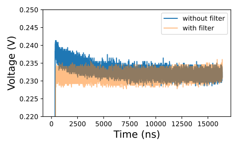
For more information about the exponential overshoot filter’s functionality, check the real-time predistortions tutorial.
FIR filter:
The FIR filter enables arbitrary predistortion of the waveform using 32 coefficients, corresponding to a 32 ns filter window. This filter can be utilized to correct short timescale distortions or for other applications as needed. To set the 32 coefficients, use the
out{x}_fir_coeffs([c1, c2, c3, ..., c32])parameter, wherexdenotes the QCM output on which the filter is activated. Each coefficient within the range of [-2, 2).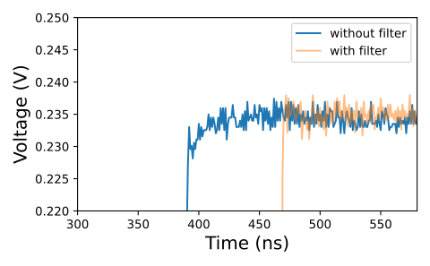
For more information about the FIR filter’s functionality, check the real-time predistortions tutorial.
Bypasses and Delays#
In addition to configuring the coefficients of the filters, each filter has a config parameter. This parameter sets
the configuration of the filter which determines the state of the filter. Through the config parameter, the filter can
be queried and set using the out{x}_ihp_config() for the inverse high-pass filter, out{x}_exp{y}_config() parameter
for the exponential overshoot filter, or the out{x}_fir_config() parameter for the FIR filter. Here, x is the index
of the QCM output on which the filter activated on (0,1,2 or 3), and y is the index of the exponential overshoot
filter (also 0, 1, 2 or 3).
The state of each filter can be set to one of these values:
'enabled': This state activates the filter, enabling its effect on the signal. This is only available in QCM.'bypassed': Selecting this state disables the filter, allowing the signal to pass through without alteration. This is available on either QCM, QRM, QCM-RF, QRM-RF.'delay_comp': This state deactivates the filter but introduces a delay in the signal equivalent to the delay incurred if the signal had passed through the filter. This is available on either QCM, QRM, QCM-RF, QRM-RF.
The 'delay_comp' option state can be utilized when a filter is enabled on one output but disabled on another, ensuring
synchronization of pulses from both outputs despite the differing filter configurations.
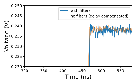
To get the delay of an output path, use out{x}_output_latency(). Then you can align all other outputs and sequencers
by activating 'delay_comp' so that signals arrive at the same time at the DUT. The following figure shows the delay
caused by each filter. There is also a base delay unless the whole filter chain is bypassed.
Note
The additional latency in the output path can cause the time-of-flight to change accordingly. Be sure to change your sequence with acquisitions to ensure that the time-of-flight is correct.
Markers and non-QCM outputs#
All the marker outputs and the Qblox QRM, QCM-RF, QRM-RF and QRC outputs do not have any filters, but might still need
to be aligned with the Qblox QCM outputs when filters are activated. So each marker and each QRM, QCM-RF, QRM-RF and QRC
output can also be optionally delay compensated using the marker{x}_ihp_config(), marker{x}_exp{y}_config(), and
marker{x}_fir_config() for marker outputs and out{x}_ihp_config(), out{x}_exp{y}_config(), and
out{x}_fir_config() for QRM, QCM-RF, QRM-RF and QRC outputs.
Since no filter is involved, there are only two possible values:
'bypassed': Disables any filtering, allowing the signal to pass through as quickly as possible.'delay_comp': Introduces a delay equivalent to the delay incurred if the signal had passed through a filter.*
Simulation#
For the exponential overshoot/undershoot filters and FIR filter, the filters may be simulated using functions from
qblox_instruments.simulations.predistortions. The functions listed here allow you to predict the behavior of the
filters given the coefficients that are applied to them, and can be used to determine the correct coefficients. These
functions only show the theoretical performance of the filters, as they are solely dependent on the coefficients. For a
more accurate representation of hardware behavior, please use the function provided by Qblox. If you do not have access
to these functions, please contact Qblox customer support.
This can be done by measuring the impulse response \(h\) of the path to the DUT perhaps using an oscilloscope, or a technique that is specific to your system (like the Cryoscope). The impulse response can then be inverted to get \(h_{inv}\). Then the simulation functions can be used to find the filter coefficient values that have the best match to the inverse impulse response.
qblox_instruments.simulations.predistortions file provides the following functions:
get_filter_delay: Returns the latency in the output line when certain filters are turned on.exponential_overshoot_correction: Simulates the behavior of the exponential overshoot filter.fir_correction: Simulates the behavior of the FIR filter.get_impulse_response: Converts a set of output path coefficients to an FIR of desired length.